
|
Hot curing by means of steam (steam curing) is limited to max. DN 400 and renovation lengths of approx. 150 m. The lining tube, which is set up by pressurized air, is charged with hot steam between approx. 60 °C to 115 °C. The electronic temperature measurements and their documentation are carried out periodically at the start and end manholes and at the intermediate manholes. Measurements are taken at the invert between the lining tube and the host … |
|
-
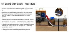
Inverted-in-place insertion of the lining tube by pressurized air
-
Installation of valves in the closed end of the lining tube in the target manhole so that the pressurized air can escape from the tube in a controlled manner during the curing process
-
Starting the curing process by blowing in a steam/air mixture
-
Excess steam escapes in a controlled manner via the valves
-
Control of the steam temperature as well as the temperatures between the lining …
|
|
-
In case of flat gradients or positional deviations (grade and alignment problems) of the pipe and a too low target temperature, the condensed water forms puddles and makes curing more difficult
-
In the presence of pressurized ground water, it can collect in low points of the pipeline and no longer be displaced by the pressurized air.
|

|
|
|
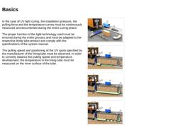
In the case of UV light curing, the installation pressure, the pulling force and the temperature curves must be continuously measured and documented during the entire curing phase. The proper function of the light technology used must be ensured during the entire process and must be adapted to the respective lining tube product and comply with the specifications of the system manual. The pulling speed and positioning of the UV spots specified by the … |
|
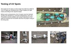
The output of UV spots is in the range from 300 W to 4000 W. The UV spots are combined into a chain of lights (UV light chain) according to the required output. Before each curing process, the UV spots must be checked visually and cleaned (e.g. removal of fingerprints, dust, etc.). The perfect overall condition and surface cleanliness of the spots are decisive for its function and thus for proper curing of the lining tube. (Image: UV light curing – … |
|
-
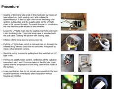
Sealing of the lining tube ends in the manholes by means of special packers (with sealing cap), which allow the implementation of the UV light chain within the lining tube and the pulling rope and the supply cable for the UV light chain to be passed through. To enable the packer installation, the liner head must be located in the manhole.
-
Lower the UV light chain into the starting manhole and insert it into the lining tube. There the lamp cable …
|
|
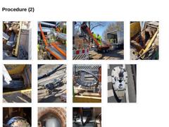
(Image: UV light curing – View of the protective foil (slip sheet)) (Image: UV light curing – Conveyor system for lining tube insertion on a tandem axle trailer) (Image: UV light curing – Winched-in-place insertion of the lining tube with the help of the conveyor system) (Image: UV light curing – Head of the lining tube to be winched-in-place) (Image: UV light curing – View into the excavation pit during the winched-in-place insertion in of the lining … |
|
Video: Installation SAERTEX-LINER H20/Pressure/Gas [YouTube] Video: SAERTEX-LINER H20 - Installation in Dresden (PFAFFINGER 2017 EN) [YouTube] (Image: Screenshot Video - Installation Saertex-Liner H20-Pressure-Gas) (Image: Screenshot Video - Installation Saertex-Liner H20 Dresden) |
|
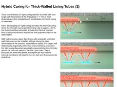
A characteristic feature of combined curing or hybrid curing is that during factory impregnation of the tubes, thermo-reactive peroxides (heat curing initiators) are added to the light-curing resins (UV initiators) system. Subsequent cure initiation is exclusively via UV radiation. The exothermic heat generated by UV curing excites the heat-cure initiators. Hybrid curing can be used, if necessary for system reasons, for thick-walled lining tubes … |
|
Since conventional UV light curing reaches its limits with very large wall thicknesses of the lining tube (> 7 mm or more depending on the manufacturer), combination or hybrid curing is used here. Here, the ongoing UV light curing activates the thermal curing. Once the UV light has heated the lining tube to approx. 60 °C, the thermoreactive peroxides activate the thermal reaction. Both curing mechanisms lead to the final polymerization of the resin … |
|
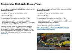
UV curing of a lining tube for a DN 1750 sewer without the addition of peroxides. -
Length of the sewer to be rehabilitated: 110 m
-
Diameter DN 1750
-
Composite wall thickness of the lining tube: 17 mm
-
UV curing system with the continuously electrically extendable UV core with a UV spot output of 6 x 4000 watts (total UV spot output of 24,000 watts)
The curing process with all parameters such as pressure, temperature, curing speed and the actual power … |
|
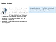
(Image: Picto Test) What is to be measured and recorded? -
Electronic recording of the pulling speed of the UV light chain, the spot function (on/off)
-
Electronic measurement and recording of the temperature curves in the surface area of the liner while the UV light chain is being pulled through
-
Measurement of the radiation intensity while the UV light chain is being pulled through
-
Measurement of the installation pressure (internal pressure) and air …
|
|
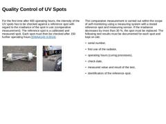
For the first time after 400 operating hours, the intensity of the UV spots has to be checked against a reference spot with regard to the irradiance of the spot in use (comparative measurement). The reference spot is a calibrated and measured spot. Each spot must then be checked after 150 further operating hours [DWAA143-3:2014]. (Image: UV light curing – UV spot) (Image: UV light curing – UV spots) The comparative measurement is carried out within … |
|
-
In the case of bend in the pipeline, there is a risk that the internal membrane will be damaged by the pull cable when the UV light chain is pulled through. This can cause air to enter the composite of the lining tube and thus damage the composite.
-
In the presence of pressurized ground water, it can collect in low points of the pipeline (grade and alignment problems) and no longer be displaced by the pressurized air.
-
The maximum wall thickness …
|
|
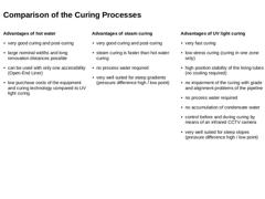
Advantages of hot water -
very good curing and post-curing
-
large nominal widths and long renovation distances possible
-
can be used with only one accessibility (Open-End Liner)
-
low purchase costs of the equipment and curing technology compared to UV light curing
Advantages of steam curing -
very good curing and post-curing
-
steam curing is faster than hot water curing
-
no process water required
-
very well suited for steep gradients (pressure difference …
|
|
(Image: 144394 - Titelbild Dokumentation)Process: Grouted-in-place lining process Title: Renovation of a masonry ovoid cross section DN 2250/1800 using the Trolining® process in the version of the Trolining® double system in modified form (without using a preliner) Promoted by: MUNLV NRW (Ministry for Environment and Nature Protection, Agriculture and Consumer Protection of the German federal state North Rhine-Westphalia) Location: Main road Limiting … |

|
Machines and equipment: For the use of the grouted-in-place lining process, the following machines and devices are primarily required: - 1 fork-lift truck
- 1 capstan winch
- 2 compressors
- 1 turning roller
- 1 unwinding construction
- 2 sealing balloons ovoid cross section DN 2250/1800
- 3 sealing balloons circular cross section DN 100
- 3 mixing units (each consisting of main mixer, steering unit and 2 post mixers)
- 2 extruder welding machine
- 2 angle grinder
- 1 drilling …
|
|
Site equipment Site equipment includes traffic safety, provision and preparation of storage surfaces for equipment and material as well as the provision of power and water supplies. Water supply is secured via a hydrant. Maintaining the drainage capability In this application case, the wastewater is pumped into a parallel overflow collector above the construction section by means of three pumps in order to maintain the drainage capability. For safety … |
|
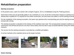
Starting excavation In the present case, a part of a section with a length of approx. 50 m is rehabilitated using the Trolining-process. Stud hoses of this size are generally pulled in via a manhole (2 x 2 m). As for this construction measure a starting excavation has already been installed for it is required for the whole construction, the stud hoses are pulled in via this starting excavation. For the installation of the starting excavation, the sewer … |

|
In this case, the renovation of a masonry sewer is to be carried out by means of a modification of the Trolining® double system. The Trolining® double system is used in order to increase the static load bearing capacity of the rehabilitated sewer. In this special application case, this process is modified in that it refrains from pulling in a preliner and the stud hoses are directly pulled into the section. Due to the grouting of the external annular … |
|
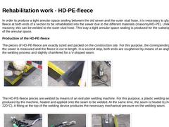
In order to produce a tight annular space sealing between the old sewer and the outer stud hose, it is necessary to glue a HD-PE-fleece at both ends of a section to be rehabilitated into the sewer due to the different materials (masonry/HD-PE). Unlike the masonry, this can be welded to the outer stud hose. This way a tight annular space sealing is produced for the subsequent grouting of the annular space. Production of the HD-PE-fleece The pieces of … |
|
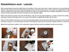
Both existing laterals must be sealed before the pulling-in of the outer stud hose in order to prevent an uncontrolled elusion of the injector in the range of the inlets during the grouting of the external annular space. This is done by a glued piece of HD-PE-fleece which is welded to the stud hoses when the laterals are later re-connected and which impedes wastewater to enter the external and internal annular space after the sewer has been put into … |
|
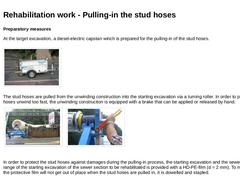
Preparatory measures At the target excavation, a diesel-electric capstan winch is prepared for the pulling-in of the stud hoses. (Image: Capstan winch) The stud hoses are pulled from the unwinding construction into the starting excavation via a turning roller. In order to prevent that the hoses unwind too fast, the unwinding construction is equipped with a brake that can be applied or released by hand. | (Image: Construction site situation (left: unwinding … |
|
|
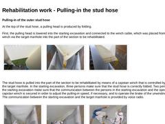
Pulling-in of the outer stud hose At the top of the stud hose, a pulling head is produced by folding. First, the pulling head is lowered into the starting excavation and connected to the winch cable, which was placed from the capstan winch via the target manhole into the part of the section to be rehabilitated. | (Image: View from below to the stud hose during the pulling-in process) | (Image: Pulling-in of the stud hose - view to the pulling head) | (… |
|