|

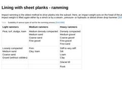
Impact ramming is the oldest method to drive planks into the subsoil. Here, an impact weight acts on the head of the plank. The impact weight is lifted again either by a winch or by a steam-, pressure- or hydraulic or diesel driven drop hammer [Schne95]. (Table: Suitability of various types of soil for the ramming process [EAU1990]) |
|

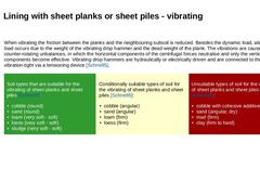
When vibrating the friction between the planks and the neighbouring subsoil is reduced. Besides the dynamic load, also a static load occurs due to the weight of the vibrating drop hammer and the dead weight of the plank. The vibrations are caused by counter-rotating unbalances, in which the horizontal components of the centrifugal forces neutralise and only the vertical components become effective. Vibrating drop hammers are hydraulically or electrically … |
|
|

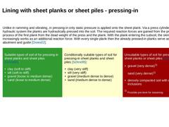
Unlike in ramming and vibrating, in pressing-in only static pressure is applied onto the sheet plank. Via a press cylinder and a hydraulic system the planks are hydraulically pressed into the soil. The required reaction forces are gained from the pressing-in process of the first plank from the dead weight of the press and the plank. With the plank entering the subsoil, the skin friction increasingly works as an additional reaction force. With every … |
|
|

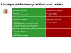
| (Image: Pros and cons) | Advantages of ramming: - efficient
- environmentally friendly
| Disadvantages of ramming: - a lot of vibration
- high level of noise
| | Advantages of vibration: - less noise
- gentle treatment of the ramming subject
- faster insertion (high economic efficiency)
- method also suitable for pulling the planks
| Disadvantage of vibrating: | | Advantage of pressing-in: - efficient
- environmentally friendly
| |
|
|

|
(Image: Pros and cons) |
When compared to sheet planks, sheet piles have the following advantages [Weiße75a]: -
They have greater dimensions and can be rammed much deeper than sheet planks
-
They posses greater section modules so that they can bridge greater support widths
-
They posses interlocking edges and are thus almost watertight
-
Because of the tensile and compressive strengths of the locks, they have a load distributing effect
|
|
|
|

|
(Image: Pros and cons) |
Advantages of sheet pile walls: -
fast progress of construction
-
excavation possible immediately after installing the piles, thus greater safety for the personnel
-
independent of weather
-
lining elements can be reused
-
no minimum requirements of stability of the soil
-
can also be used in groundwater
-
less personnel requirement
-
simple equipment installation
-
transfer of vertical forces via skin friction forces possible
|
|
|
|

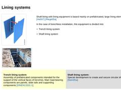
(Image: Centrally supported trench lining system) (Image: Starting pit of lining systems for microtunneling) Shaft lining with lining equipment is based mainly on prefabricated, large lining elements of steel [Heß97] [Riege00a]. In the case of trenchless installation, this equipment is divided into: -
Trench lining system
-
Shaft lining system
|
Trench lining system:
Assembly of prefabricated components intended for the support of the vertical faces of … |
|
|
|

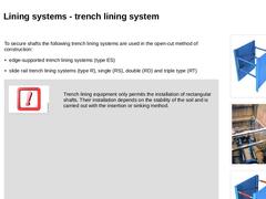
To secure shafts the following trench lining systems are used in the open-cut method of construction: -
edge-supported trench lining systems (type ES)
-
slide rail trench lining systems (type R), single (RS), double (RD) and triple type (RT)
|
|
(Image: Slide rail trench lining system) |
|
(Image: Starting pit with trench lining system ) (Image: Edge-supported trench lining system) |
|
|
(Image: Attention!) |
Trench lining equipment only permits the installation … |
|
|
|

|
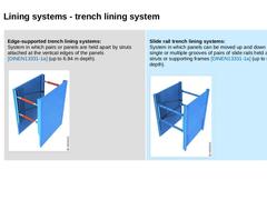
Edge-supported trench lining systems:
System in which pairs or panels are held apart by struts attached at the vertical edges of the panels [DINEN13331-1a] (up to 6.84 m depth). (Image: Edge-supported trench lining system)
|
Slide rail trench lining systems:
System in which panels can be moved up and down in single or multiple grooves of pairs of slide rails held apart by struts or supporting frames [DINEN13331-1a] (up to 8.26 m depth). (Image: Slide … |
|
|

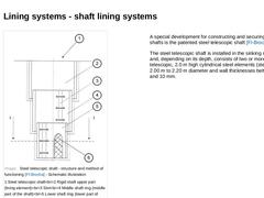
(Image: Steel telescopic shaft - structure and method of functioning [FI-Brocha] - Schematic illustration) A special development for constructing and securing circular shafts is the patented steel telescopic shaft [FI-Brocha]. The steel telescopic shaft is installed in the sinking method and, depending on its depth, consists of two or more telescopic, 2.0 m high cylindrical steel elements (steel rings) of 2.00 m to 2.20 m diameter and wall thicknesses … |
|

| (Image: Attention!)
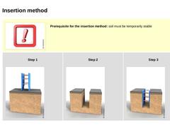
Prerequisite for the insertion method: soil must be temporarily stable | | Step 1 (Image: Installation of edge-supported trench lining systems (ES) in the insertion method - Working step 1: Preparation of trench lining system with height corresponding to the depth of the shaft +10 cm and with a width corresponding to that of the shaft)
| Step 2 (Image: Installation of edge-supported trench lining systems (ES) in the insertion method - … |
|
|

| (Image: Attention!)
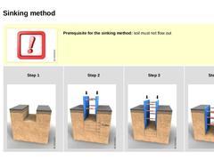
Prerequisite for the sinking method: soil must not flow out | | Step 1 (Image: Installation of edge-supported trench lining systems (ES) in the sinking method - Working step 1: Excavation corresponding to local conditions as far as possible)
| Step 2 (Image: Installation of edge-supported trench lining systems (ES) in the sinking method - Working step 2: Insertion, stepped excavation (maximum of 0.50 m) and sinking the trench lining system)
|
|
|

| (Image: Pros and cons) |
|
Advantages of lining systems: - can be used in almost all soils
- can be used several times without modification
- short installation time due to mechanical installation and removal
- no vibrations, low noise emissions
|
|
Disadvantages of lining systems: - limited applicability in the region of crossing lines (additional measures required)
- lifting devices required
- utilization only above the, possibly lowered, groundwater level
|
|
|

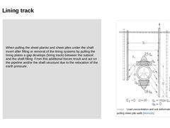
When pulling the sheet planks and sheet piles under the shaft invert after filling or removal of the lining systems by pulling the lining plates a gap develops (lining track) between the subsoil and the shaft filling. From this additional forces result and act on the pipeline and/or the shaft structure due to the relocation of the earth pressure. |
(Image: Load concentration and soil deformation when pulling sheet pile walls [Hornu91]) |
|
|

|
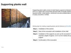
(Image: Supporting planks wall [FI-Emun])
Supporting plank walls consist of steel beams spaced at between 2.0 m and 3.5 m apart with a horizontal stressed infill of wooden planks, squared timber, sheet planks, reinforced concrete prefabrications, insitu or spray concrete or similar. (Table: Working steps hen creating a supporting planks wall with reference to [Schne95] [FI-Steina]) |
|
|

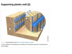
(Image: Supporting planks wall) |
|

| (Image: Pros and cons) | | Advantages of supporting planks walls: - adaptable to obstacles such as pipelines, shafts, old foundations and others
- usable in nearly all types of soils
- construction components re-usable
- economic efficiency
| | Disadvantages of supporting planks walls: - soft lining, danger of subsidence for neighbouring structures or traffic areas
- due to limited transport lengths of the beams not usable for arbitrary depths (at best extendable …
|
|
|

|
|

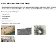
Non-removable (lost) linings are understood in the case of trenchless installation to be covering, bracing and anchoring structures which are left partially or wholly in the subsoil after completion of the jacking or construction works. The non-removable types of lining are: (Image: (Bored) pile wall) (Image: Shaft securing with spray … |
|

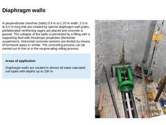
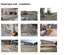
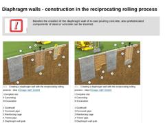
In perpendicular trenches (slats) 0.4 m to 1.20 m width, 2.0 m to 5.0 m long that are created by special diaphragm wall grabs, prefabricated reinforcing cages are placed and concrete is poured. The collapse of the walls is prevented by a filling with a supporting fluid with thixotropic properties (Bentonite suspension). Horizontal concrete sections are limited by means of formwork pipes or similar. The concreting process can be carried out in-line … |
|

(Image: Construction of the baffle wall (reinforced concrete) on both sides of the slot for the diaphragm wall excavator) (Image: Completed baffle wall for the diaphragm wall excavator) (Image: Excavation of the diaphragm wall - Diaphragm wall excavator) (Image: Detail of diaphragm exhibitor) (Image: Reinforcement cages for the diaphragm wall) (Image: Concreting the diaphragm wall) (Image: Chipping of the top of the baffle and diaphragm wall, exposing … |
|

|
(Image: Attention!)
Besides the creation of the diaphragm wall of in-cast pouring concrete, also prefabricated components of steel or concrete can be inserted. |
|
|
|
(Image: Creating a diaphragm wall with the reciprocating rolling process - step 1) |
(Image: Creating a diaphragm wall with the reciprocating rolling process - step 2) |
|
(Video: Excavator in diaphragm wall operation) |
|

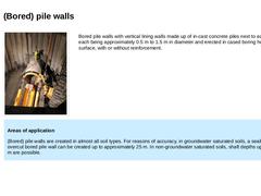
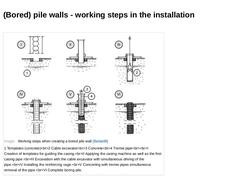
(Image: Starting shaft with bored pile wall) Bored pile walls with vertical lining walls made up of in-cast concrete piles next to each other, each being approximately 0.5 m to 1.5 m in diameter and erected in cased boring holes from the surface, with or without reinforcement. |
|
Areas of application (Bored) pile walls are created in almost all soil types. For reasons of accuracy, in groundwater saturated soils, a sealing overcut bored pile wall can be … |
|
|

|
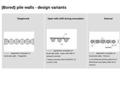
Tangierend
(Image: Application examples of bored pile walls - Tangential) |
Open with infill during excavation
(Image: Application examples of bored pile walls - Open with infill of sprayed concrete) |
Overcut
(Image: Application examples of bored pile walls - Overcut) |
|
|

(Image: Working steps when creating a bored pile wall [Balda88]) |