|
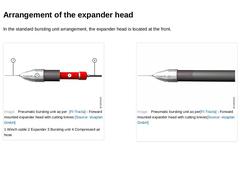
In the standard bursting unit arrangement, the expander head is located at the front. (Image: Pneumatic bursting unit as per [FI-Tracta] - Forward mounted expander head with cutting knives) (Image: Pneumatic bursting unit as per [FI-Tracta] - Forward mounted expander head with cutting knives) |
|
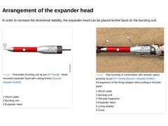
In order to increase the directional stability, the expander head can be placed further back on the bursting unit. (Image: Pneumatic bursting unit as per [FI-Tracta] - Read mounted expander head with cutting knives) (Image: Pipe bursting in combination with annular space grouting as per [FI-Tracta] - Arrangement of the lining adaptor when pulling-in discrete pipes) |
|
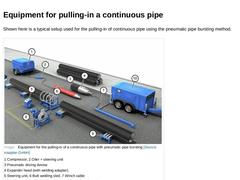
Shown here is a typical setup used for the pulling-in of continuous pipe using the pneumatic pipe bursting method. (Image: Equipment for the pulling-in of a continuous pipe with pneumatic pipe bursting) |
|
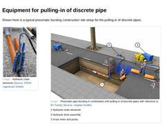
Shown here is a typical pneumatic bursting construction site setup for the pulling-in of discrete pipes. (Image: Hydraulic chain tensioner) (Image: Pneumatic pipe bursting in combination with pulling-in of discrete pipes with reference to [FI-Tracta]) |
|
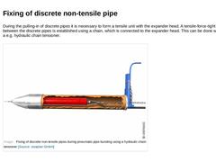
During the pulling-in of discrete pipes it is necessary to form a tensile unit with the expander head. A tensile-force-tight connection between the discrete pipes is established using a chain, which is connected to the expander head. This can be done with the help of a e.g. hydraulic chain tensioner. (Image: Fixing of discrete non-tensile pipes during pneumatic pipe bursting using a hydraulic chain tensioner) |
|
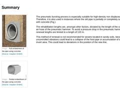
(Image: Full embedment of the pipe using concrete) (Image: Partial embedment of the pipe using concrete) The pneumatic bursting process is especially suitable for high-density non displaceable soils. Therefore, it is also used in instances where the old pipe is partially or completely surrounded with concrete (Fig.). The rehabilitation lengths are, amongst other factors, dictated by the length of the compressed air hose of the pneumatic hammer. To avoid … |
|
Advantages: -
High operating speed
-
Not dependant on the density of the soil in the embedment
Disadvantages: -
Pneumatic bursting unit can normally only be deployed from one access pit/excavation.
-
Pneumatic force introduction has a major effect on the surrounding subsoil and adjoining pipelines:
-
Uncontrollable, advancing destruction or collapse of the host pipeline,
-
Unintentional compaction of the soil in the embedment resulting in the settlement …
|
|
|
|
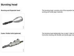
Bursting and Expander head (Image: Bursting and expanding body for static pipe bursting) The bursting head consists only of the expander head when working with brittle pipe materials. Cutter / Roller knife (optional) (Image: Roller knife for static pipe bursting) The bursting head additionally has a cutter / roller knife at the front when working with flexible and ductile pipe materials. |
|
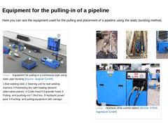
Here you can see the equipment used for the pulling and placement of a pipeline using the static bursting method. (Image: Equipment for pulling-in a continuous pipe using static pipe bursting) (Image: Static pipe bursting - Expander head) (Image: Static pipe bursting - pushing/pulling carriage) (Image: Pushing- and pulling-equipment with carriage) (Image: Hydraulic drive control station) |
|
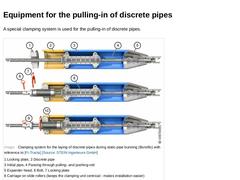
A special clamping system is used for the pulling-in of discrete pipes. (Image: Clamping system for the laying of discrete pipes during static pipe bursting (Burstfix) with reference to [FI-Tracta] [Image: S&P GmbH]) |
|
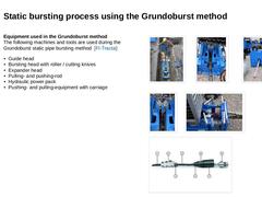
Equipment used in the Grundoburst method
The following machines and tools are used during the Grundoburst static pipe bursting method [FI-Tracta]: -
Guide head
-
Bursting head with roller / cutting knives
-
Expander head
-
Pulling- and pushing-rod
-
Hydraulic power pack
-
Pushing- and pulling-equipment with carriage
(Image: Grundoburst process [FI-Tracta] - Pushing- and pulling-equipment with carriage in the starting excavation) (Image: Grundoburst method-… |
|
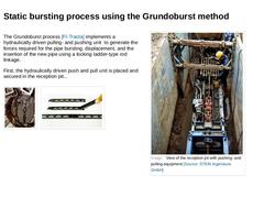
The Grundoburst process [FI-Tracta] implements a hydraulically driven pulling- and pushing unit to generate the forces required for the pipe bursting, displacement, and the insertion of the new pipe using a locking ladder-type rod linkage. First, the hydraulically driven push and pull unit is placed and secured in the reception pit... (Image: Pulling- and pushing-rod passing through the manhole) (Image: Installation of the pulling- and pushing-rod [… |
|
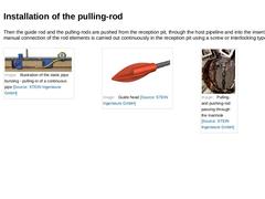
Then the guide rod and the pulling-rods are pushed from the reception pit, through the host pipeline and into the insertion pit. The manual connection of the rod elements is carried out continuously in the reception pit using a screw or interlocking type system. (Image: Illustration of the static pipe bursting - pulling-in of a continuous pipe) (Image: Pulling- and pushing-rod passing through the manhole) |
|
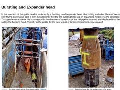
In the insertion pit the guide head is replaced by a bursting head (expander head plus cutting and roller blades if necessary). The new HDPE-continuous pipe is then subsequently fixed to the bursting head via an expanding nipple or a PE-connection adapter.
Through the retraction of the bursting rod in the direction of reception pit the old pipe is ruptured and displaced into the surrounding soil by the bursting head. Thereby is the profile for the … |
|
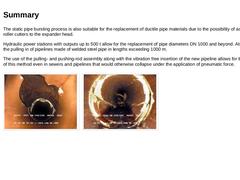
The static pipe bursting process is also suitable for the replacement of ductile pipe materials due to the possibility of adding knife/roller cutters to the expander head. Hydraulic power stations with outputs up to 500 t allow for the replacement of pipe diameters DN 1000 and beyond. Also possible is the pulling in of pipelines made of welded steel pipe in lengths exceeding 1000 m. The use of the pulling- and pushing-rod assembly along with the vibration … |
|
Advantages: -
No vibrations
-
No new pit construction is required when using discrete pipe matched to the size of the manhole structure.
-
Can also be used with flexible and ductile pipe materials.
-
The use of the pulling- and pushing-rod assembly along with the vibration free insertion of the new pipeline allows for the application of this method even in sewers and pipelines that would otherwise collapse under the application of pneumatic force.
|

|
|
|
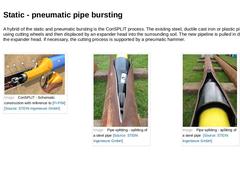
A hybrid of the static and pneumatic bursting is the ConSPLIT process. The existing steel, ductile cast iron or plastic pipeline is cut using cutting wheels and then displaced by an expander head into the surrounding soil. The new pipeline is pulled in directly behind the expander head. If necessary, the cutting process is supported by a pneumatic hammer. (Image: ConSPLIT - Schematic construction with reference to [FI-PIM] [Image: S&P GmbH]) |

|
|
|
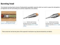
The hydraulic bursting head consists of hydraulically expandable segments which are used to rupture the old pipeline and displace its fragments into the surrounding soil, and thus expand the cross section. (Image: Hydraulic pipe bursting - Bursting head with 3 expandable segments (closed)) (Image: Hydraulic pipe bursting - Bursting head with 3 expandable segments (opened)) There exists the risk that the joints of the expansion mechanism may become blocked … |
|
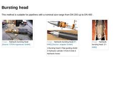
This method is suitable for pipelines with a nominal size range from DN 200 up to DN 400 . (Image: Hydraulic bursting head) (Image: Hydraulic bursting head) (Image: Hydraulic bursting head [FI-KMG]) |
|
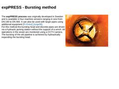
The expPRESS process was originally developed in Sweden and is available in four machine versions ranging in size from DN 180 to DN 900. It can also be used with larger pipes using additional equipment [FI-Entre] [Jürge90].
For this method the bursting head and discrete pipes are driven via a hydraulic jacking station without the support of a winch. All operations in the sewer are monitored using a CCTV camera. The bursting of the old pipeline is … |
|
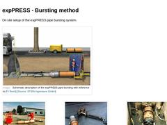
On site setup of the expPRESS pipe bursting system. (Image: Schematic description of the expPRESS pipe bursting with reference to [FI-Teerb] [Image: S&P GmbH]) (Image: expPRESS pipe bursting [FI-Teerb] - In-situ situation) (Image: expPRESS pipe bursting [FI-Teerb] - Bursting head with hydraulic jacking arrangement) (Image: expPRESS pipe bursting [FI-Teerb] - bursting head in the starting pit) |
|
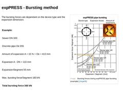
The bursting forces are dependant on the device type and the expansion dimension. |
Example: |
|
Sewer DN 300 |
|
Discrete pipe De 355 |
|
Amount of expansion A = 15 % + De = 410 mm |
|
Expansion A - DN = 110 mm |
|
Expansion/Segment 55 mm |
|
Max. bursting force/Segment 180 kN |
|
Total bursting force 360 kN |
(Image: Bursting forces during expPRESS pipe bursting (example) [Jürge05]) |