
|
Schöne Bäume waren einst Zeichen für Reichtum und Vitalität einer Stadt. Nachdem diese Erkenntnis lange Zeit in Vergessenheit geraten war und Bäume z.B. der Verbesserung des Straßenverkehrs geopfert wurden, werden seit einigen Jahren und in zunehmender Tendenz in den Städten und Gemeinden der Bundesrepublik Deutschland wieder Maßnahmen zur Stadtbegrünung - selbst auch im Zusammenhang mit der Verkehrsberuhigung - geplant und ausgeführt.
Die Bedeutung … |

|
(Bild: Varianten der grabenlosen Verlegung von Leitungen)
Bei der grabenlosen Verlegung von Leitungen kann prinzipiell unterschieden werden zwischen der Verlegung einzelner Leitungen (Einzelverlegung) oder der gemeinsamen Verlegung mehrerer Leitungen auch unterschiedlicher Art in gleicher Trasse und Gradiente (Mehrfach Verlegung).
Einen Überblick über die weitere Untergliederung dieser beiden Varianten vermittelt Bild 2. |

|
Unter Einzelverlegung wird nachfolgend die separate Verlegung einzelner Leitungen in vorgegebener Trasse und Gradiente (z.B. im Straßenquerschnitt nach DIN 1998 [DIN1998] (Abschnitt 1.2)) verstanden. Sie kann erfolgen durch (Bild 2) : - Erdverlegung
- Verlegung im Schutzrohr
|

|
Unter dem Begriff Erdverlegung wird nachfolgend der unmittelbare Einbau der Produktrohrleitung in den grabenlos aufgefahrenen unterirdischen Hohlraum verstanden. Die Produktrohrleitung muss dabei die Belastungen im Bau- und im Betriebszustand (Abschnitt 14) aufnehmen können. |

|
(Bild: Verlegung einer Wasserleitung im Schutzrohr (Ringraum verfüllt) in Anlehnung an [DVGWAGW307] [Bild: S&P GmbH]) Das Schutzrohr hat die Aufgaben die Produktrohrleitung bzw. das Kabel aufzunehmen, diese gegenüber äußeren Beanspruchungen zu schützen und im Versagensfall als Schutzhülle der Produktrohrleitung bzw. das Kabel zu fungieren. Darüber hinaus dient es im Zusammenhang mit der geschlossenen Bauweise verfahrensabhängig zur Herstellung und/… |
|
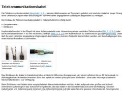
Die Telekommunikationskabel (Abschnitt 1.1.5.1) werden üblicherweise auf Trommeln geliefert und sind als möglichst langer Strang ohne Unterbrechungen unter Beachtung der vom Hersteller angegebenen zulässigen Biegeradien zu verlegen.
Der Einbau der Telekommunikationskabel in Kabelschutzrohre erfolgt durch - Einziehen oder
- Einblasen.
Kupferkabel werden in der Regel mit einer Kabelzugwinde unter Verwendung eines speziellen Ziehstrumpfes (Bild 2.1.2.1)
|
|
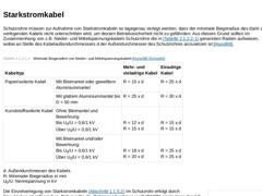
Schutzrohre müssen zur Aufnahme von Starkstromkabeln so lagegenau verlegt werden, dass der minimale Biegeradius des darin zu verlegenden Kabels nicht unterschritten wird, um dessen Betriebssicherheit nicht zu gefährden. Aus diesem Grund sollten im Zusammenhang von z.B. Nieder- und Mittelspannungskabeln Schutzrohre die in Tabelle 2.1.2.2 genannten Radien aufweisen, wobei an Stelle des Kabelaußendurchmessers d der Außendurchmesser des Schutzrohres … |
|
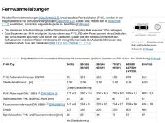
(Bild: Einziehen eines FHK mit Gleitkufen in ein Schutzrohr [FI-Brugg]) Flexible Fernwärmeleitungen (Abschnitt 1.1.3), insbesondere Fernheizkabel (FHK), werden in der Regel jeweils in ein Schutzrohr eingezogen (Abschnitt 2.2). Dabei sind, neben den in Abschnitt 2.1.2 erwähnten, zusätzlich folgende Aspekte zu beachten [FI-Brugg] : - Die maximale Schutzrohrlänge darf bei Standardausführung des FHK maximal 30 m betragen.
- Das Einziehen der FHK erfolgt …
|
|
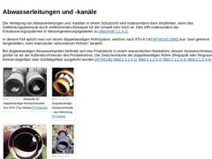
Die Verlegung von Abwasserleitungen und -kanälen in einem Schutzrohr wird insbesondere dann empfohlen, wenn das Gefährdungspotenzial durch exfiltrierendes Abwasser für die Umwelt sehr hoch ist. Dies trifft insbesondere bei Entwässerungssystemen in Wassergewinnungsgebieten zu (Abschnitt 1.1.4.1).
In diesem Fall spricht man von einem doppelwandigen Rohrsystem, welches nach ATV-A 142 [ATVA142:2000] aus "zwei getrennt hergestellten, nicht miteinander …
|
|
Ob eine Gas- oder Wasserleitung bei der Kreuzung von Verkehrswegen in einem Schutzrohr verlegt wird, bestimmen im Wesentlichen die verwendeten Werkstoffe bzw. die Verbindungsarten der Produktrohre. Generell sind zunächst Sicherheitsgründe für die jeweilige Ausführung maßgebend, so soll z.B. ein Schutzrohr für eine Wasserleitung bei einem etwaigen Bruch derselben ein Unterspülen des Verkehrsweges durch austretendes Wasser verhindern. |

|
Beim nachträglichen Einbringen von Produktrohren in zuvor grabenlos verlegte Schutzrohre (Abschnitt 2.1.2) unterscheidet man in Abhängigkeit von der dabei auftretenden Beanspruchung der einzelnen Rohre bzw. der Rohrleitung folgende Varianten [Stein83c] : - Einziehverfahren
- Einziehen eines Rohrstranges aus Rohren mit zugkraftschlüssiger Verbindung
- Einziehen eines Rohrstranges aus Rohren mit druckkraftschlüssiger Verbindung (ziehend/schiebend)
- Einziehen …
|
|
|
|
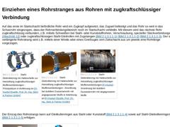
Auf das erste im Startschacht befindliche Rohr wird ein Zugkopf aufgesetzt, das Zugseil befestigt und das Rohr so weit in das Schutzrohr eingezogen, dass der Rohrverbindungsbereich noch im Startschacht verbleibt. Mit diesem wird das nächste Rohr zugkraftschlüssig verbunden, z.B. mittels Schweißen bei Stahl- oder Kunststoffrohren, Verschraubung, spezieller Steckverbindungen (Abschnitt 13) oder zugkraftschlüssigen Stahl-Gleitrollen mit Zugstangen … |
|
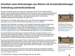
| | | | | (Bild: Rohrzuggeräte (WIMAG) [FI-WIMAG] - Mit Traverse) | | (Bild: Rohrzuggeräte (WIMAG) - Mit Rundgreifer) |
Bei dieser Methode werden das Zugseil vom Zielschacht aus durch die Produktrohrleitung gezogen und die Zugkraft über eine jeweils am Ende des letzten noch im Startschacht befindlichen Rohres angebrachte Druckplatte oder Traverse in den bereits zusammengefügten Rohrstrang eingeleitet. Die Rohre werden dabei nur auf Axialdruck beansprucht, … |
|
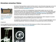
Bei diesem Einbringverfahren werden die Rohre einzeln in das Schutzrohr eingezogen und vor Ort miteinander verbunden. Die Arretierung des Rohrstranges erfolgt durch Festsetzen des ersten Rohres im Zielschacht (Abschnitt 2.1.3.1.3).
Zum Einziehen von Rohren mit nichtbegehbaren Querschnitten bedient man sich z.B. eines aufblasbaren Packers oder eines speziellen Einziehkörpers, auf den das Rohr aufgeschoben wird und der am Ende mit einer Aufkantung … |
|
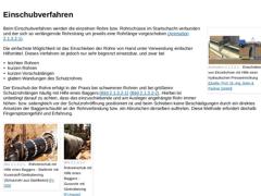
Beim Einschubverfahren werden die einzelnen Rohre bzw. Rohrschüsse im Startschacht verbunden und der sich so verlängernde Rohrstrang um jeweils eine Rohrlänge vorgeschoben (Abschnitt 2.1.3.2).
Die einfachste Möglichkeit ist das Einschieben der Rohre von Hand unter Verwendung einfacher Hilfsmittel. Dieses Verfahren ist jedoch nur sehr begrenzt einsetzbar, und zwar bei - leichten Rohren
- kurzen Rohren
- kurzen Vorschublängen
- glatten Wandungen des Schutzrohres
|
|
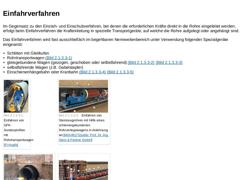
Im Gegensatz zu den Einzieh- und Einschubverfahren, bei denen die erforderlichen Kräfte direkt in die Rohre eingeleitet werden, erfolgt beim Einfahrverfahren die Krafteinleitung in spezielle Transportgeräte, auf welche die Rohre aufgelegt oder angehängt sind.
Das Einfahrverfahren wird fast ausschließlich im begehbaren Nennweitenbereich unter Verwendung folgender Spezialgeräte eingesetzt: - Schlitten mit Gleitkufen
- Rohrtransportwagen (Bild 2.1.3.3)…
|
|
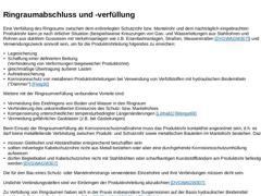
Eine Verfüllung des Ringraums zwischen dem erdverlegten Schutzrohr bzw. Mantelrohr und dem nachträglich eingebrachten Produktrohr kann je nach örtlicher Situation (beispielsweise Kreuzungen von Gas- und Wasserleitungen aus Stahlrohren und Rohren aus duktilem Gusseisen mit Verkehrsanlagen wie z.B. Eisenbahnanlagen, Straßen, Wasserstraßen [DVGWAGW307]) und Verwendungszweck sinnvoll sein, um für die Produktrohrleitung folgendes zu erreichen:
|

|
(Bild: Varianten der grabenlosen Verlegung von Leitungen)
Unter Mehrfachverlegung versteht man die gemeinsame Verlegung mehrerer Leitungen (nacheinander oder gleichzeitig) auch unterschiedlicher Art in gleicher Trasse und Gradiente. Sie kann erfolgen durch (Bild 2.2) : - Erdverlegung (Abschnitt 2.2.1)
- Verlegung im Mantelrohr (Abschnitt 2.2.2)
- Verlegung im Leitungskanal (Abschnitt 2.2.3)
- Verlegung im Leitungsgang (Abschnitt 2.2.4)
- Verlegung in Produktrohrleitungen (…
|
|
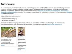
Im Zusammenhang mit der Mehrfachverlegung wird nachfolgend unter dem Begriff Erdverlegung das unmittelbare gemeinsame Einziehen mehrerer Produktrohrleitungen und/oder Kabel in den aufgefahrenen unterirdischen, vorübergehend standfesten Hohlraum mit Hilfe eines Verfahrens des grabenlosen Leitungsbaus (Abschnitt 5) (Abschnitt 6) (Abschnitt 7.1) (Abschnitt 8.1) (Abschnitt 9.1) (Abschnitt 16) verstanden. Die Leitungen müssen dabei die Belastungen im …
|

|
(Bild: Varianten der grabenlosen Verlegung von Leitungen)
Mantelrohre sind unterirdische nichtbegehbare oder begehbare Rohrleitungen zur nachträglichen Aufnahme mehrerer Produktleitungen oder Schutzrohre gleicher oder unterschiedlicher Art. Im Zusammenhang mit der geschlossenen Bauweise dienen sie verfahrensabhängig zur Herstellung und/oder Stützung des aufgefahrenen Hohlraumes. In diesem Anwendungsfall müssen Mantelrohre auch die Belastungen im … |
|
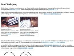
Bei der losen Verlegung von Leitungen, in der Regel Kabel, werden diese entweder separat nacheinander oder gemeinsam (nichtgebündelt (Abschnitt 2.2.1) in einem Arbeitsgang eingezogen oder eingeblasen (Abschnitt 2.1.2). Dabei wird bewusst auf die Einhaltung von Leitungsabständen und -anordnungen verzichtet, um die Möglichkeit zu haben, zu einem späteren Zeitpunkt u.U. einzelne Leitungen durch Herausziehen zu ersetzen (Bild 2.2.2.1) (Bild 2.2.2.1).… |
|
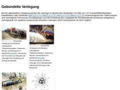
Bei der gebündelten Verlegung werden die Leitungen in bestimmten Abständen mit Hilfe von z.B. Kunststoffklebebändern, Kabelbindern oder Gleitkufen (Bild 2.2.2.2) (Bild 2.2.2.2) (Bild 2.2.2.2) (Bild 2.2.2.2) zusammengeschnürt. Damit werden eine kontrollierte Führung der Einzelleitungen und die Einhaltung des vorgegebenen Bündelaußendurchmessers weitgehend sichergestellt. Ein späteres Auswechseln einzelner Leitungen durch Herausziehen ist nicht möglich.
|

|
Bei der Blockverlegung werden die einzelnen Produkt- und Schutzrohrleitungen durch Mehrfachschellen oder Abstandhalter kontrolliert angeordnet sowie fixiert und mit Hilfe von Rollen oder Gleitkufen (Bild 2.2.2.3) (Bild 2.2.2.3) (Bild 2.2.2.3) (Bild 2.2.2.3) in das Mantelrohr eingebracht (Abschnitt 2.1.3). | (Bild: Blockverlegung mit Mehrfachschellen im Mantelrohr auf Gleitkufen (rechts) und Rollen (links) [FI-DSI]) | (Bild: Vortrieb eines Mantelrohres … |
|
|
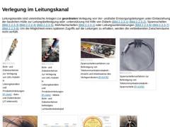
Leitungskanäle sind unterirdische Anlagen zur geordneten Verlegung von Ver- und/oder Entsorgungsleitungen unter Einbeziehung der baulichen Hülle zur Leitungsbefestigung oder -unterstützung mit Hilfe von Dübeln (Bild 2.2.3) (Bild 2.2.3), Spannschellen (Bild 2.2.3) (Bild 2.2.3) (Bild 2.2.3), Mehrfachschellen (Bild 2.2.2.3) oder Leitungsunterstützungen (Bild 2.2.3) (Bild 2.2.3) (Bild 2.2.3). Um die Möglichkeit eines späteren Zugriffs auf die Leitungen … |