|

|
(Bild: Einbringen des Roboters in den Einsteigschacht) |
(Bild: Positionieren des Roboters unter Kamerabeobachtung) |
|
(Bild: Auffräsen des Risses mit Hilfe des KA-TE-Fräsroboter) |
(Bild: Roboter mit Injektionskopf) |
|
(Bild: Verpressen eines Risses mit dem KA-TE-Spachtelroboter) |
(Bild: Roboter mit Manschette) |
|
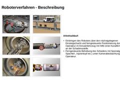
Arbeitsablauf: -
Einbringen des Roboters über den nächstgelegenen Einsteigschacht und ferngesteuerte Positionierung durch den Operateur im Einsatzfahrzeug …
|
|
|
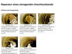
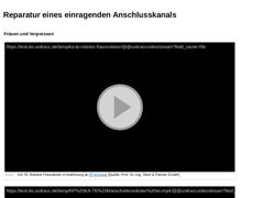
Fräsen und Verspachteln |
(Bild: Reparatur eines einragenden Anschlusskanals mit dem KA-TE-System - Abfräsen des einragenden Anschlusskanals bündig zur Rohrinnenwand [FI-Kunsta])
|
(Bild: Reparatur eines einragenden Anschlusskanals mit dem KA-TE-System - Abfräsen des einragenden Anschlusskanals bündig zur Rohrinnenwand [FI-Kunsta])
|
(Bild: Reparatur eines einragenden Anschlusskanals mit dem KA-TE-System - Nach Beendigung der Abfräsarbeiten [FI-Kunsta])
|
|
|
|
Video: KA-TE Manschette [Quelle: S&P GmbH]. Dieses interaktive Objekt ist ausschließlich in der Online-Version des Moduls sichtbar. Video: KA-TE System [Quelle: S&P GmbH]. Dieses interaktive Objekt ist ausschließlich in der Online-Version des Moduls sichtbar. |
Fräsen und Verpressen |
|
(Video: KA-TE Roboter Fräsroboter) Video: KA-TE Fräsen [Quelle: S&P GmbH]. Dieses interaktive Objekt ist ausschließlich in der Online-Version des Moduls sichtbar. |
|
(Video: … |
|
|
|
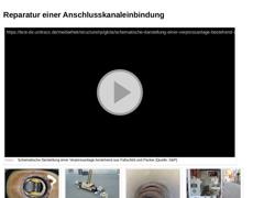
(Video: Schematische Darstellung einer Verpressanlage bestehend aus Faltschild und Packer) |
Video: Schematische Darstellung einer Verpressanlage bestehend aus Faltschild und Packer [Quelle: S&P GmbH]. Dieses interaktive Objekt ist ausschließlich in der Online-Version des Moduls sichtbar.
|
(Bild: Sanierung einer Anschlusskanaleinbindung - Blick auf den eingefahrenen Packer) |
(Bild: Sanierung einer Anschlusskanaleinbindung - Ausgefahrener Packer) |
(… |
|
|
|
|
(Bild: Auffräsen des Risses mit Hilfe des KA-TE-Fräsroboter)
|
(Bild: Ausfräsen des Risses mit Hilfe des KA-TE-Fräsroboters)
|
|
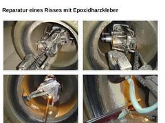
(Bild: Verpressen des Risses mit Hilfe des KA-TE-Spachtelroboters)
|
(Bild: Glattstrich des verpressten Risses mit Hilfe des KA-TE-Spachtelroboters)
|
|
|
|
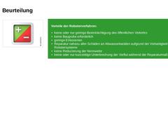
| (Bild: Plus/Minus) | Vorteile der Roboterverfahren: - keine oder nur geringe Beeinträchtigung des öffentlichen Verkehrs
- keine Baugrube erforderlich
- geringe Emissionen
- Reparatur nahezu aller Schäden an Abwasserkanälen aufgrund der Vielseitigkeit der Robotersysteme
- keine Reduzierung der Nennweite
- keine oder nur kurzzeitige Unterbrechung der Vorflut während der Reparaturmaßnahme
|
|

|
| (Bild: Plus/Minus) | Nachteile der Roboterverfahren: - Ausrüstung ist relativ teuer in der Anschaffung
- Großes Fachkönnen des Operateurs erforderlich
- Präzise Beurteilung des Schadens erforderlich
|
|
|
|
|
|
Abdichtungsverfahren dienen zur örtlich begrenzten Abdichtung von Kanälen zur Wiederherstellung der Wasserdichtheit oder ggf. zur Stabilisierung der Tragfähigkeit. |
|
(Bild: Statik) |
|
(Bild: Dichtheit) |
|
|
|
|
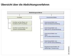
(Bild: Übersicht über die Abdichtungsverfahren von innen mittels Innenmanschetten) |
|
|
|
|
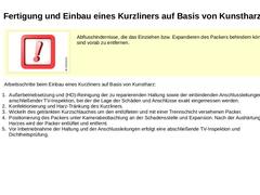
Diese Verfahrensgruppe ist charakterisiert durch eine mit Kunstharz getränkte Gewebemanschette, die mit Hilfe eines mit Luft, Wasser oder Dampf aufblasbaren Packers über den Schacht zur Schadensstelle im Kanal transportiert und an die Kanalinnenwand gepresst wird und unter Aufrechterhaltung des Packerdruckes in situ erhärtet. (Video: Arbeitsgänge beim Einbau eines Kurzliners) (Bild: Kurzschlauch auf der Basis von Kunstharz - Packer mit aufgelegtem … |
|
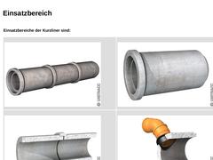
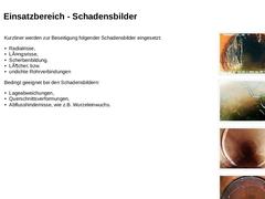
Einsatzbereiche der Kurzliner sind: | | (Bild: Haltungsabschnitte)
| (Bild: Einzelrohre)
| | (Bild: Rohrverbindungen)
| (Bild: Einbindungen von Anschlussleitungen)
|
|
|
|
Kurzliner werden zur Beseitigung folgender Schadensbilder eingesetzt: - Radialrisse,
- Längsrisse,
- Scherbenbildung,
- Löcher, bzw.
- undichte Rohrverbindungen
Bedingt geeignet bei den Schadensbildern: - Lageabweichungen,
- Querschnittsverformungen,
- Abflusshindernisse, wie z.B. Wurzeleinwuchs.
| |
(Bild: Wurzeleinwuchs im Bereich einer Rohrverbindung #literature( '0000009687'))
|
|
(Bild: Scherbenbildung in einem Steinzeugrohr; Scherben sind noch im Rohrverband [… |
|
|
|
| Wichtig: Abflusshindernisse, die das Einziehen bzw. Expandieren des Packers behindern können, sind vorab zu entfernen. | |
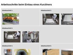
Arbeitsschritte beim Einbau eines Kurzliners auf Basis von Kunstharz: - Außerbetriebsetzung und (HD)-Reinigung der zu reparierenden Haltung sowie der einbindenden Anschlussleitungen mit anschließender TV-Inspektion, bei der die Lage der Schäden und Anschlüsse exakt eingemessen werden.
- Konfektionierung und Harz-Tränkung des Kurzliners.
|
|
|
Arbeitsschritt 1: (Bild: Spül-Saugfahrzeug zur Reinigung von Abwasserkanälen)
| Arbeitsschritt 2: |
(Bild: Tränkung des Kurzliners)
|
(Bild: Tränkung des Kurzliners)
|
| Arbeitsschritt 3: |
(Bild: Wickeln des getränkten Kurzliners um den entlüfteten Packers)
|
(Bild: Wickeln des getränkten Kurzliners um den entlüfteten Packer)
|
| Arbeitsschritt 4: |
(Bild: Einbringen des Packers mit dem getränkten Kurzliner in den Einsteigschacht)
|
(Bild: Ausgehärteter Kurzliner)
|
|
|
|
|
(Bild: Plus/Minus) |
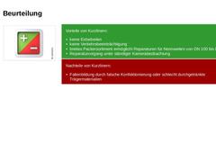
Vorteile von Kurzlinern: -
keine Erdarbeiten
-
keine Verkehrsbeeinträchtigung
-
breites Packersortiment ermöglicht Reparaturen für Nennweiten von DN 100 bis DN 800
-
Reparaturvorgang unter ständiger Kamerabeobachtung
|
|
Nachteile von Kurzlinern: -
Faltenbildung durch falsche Konfektionierung oder schlecht durchgetränkte Trägermaterialien
|
|
|
|
|
|
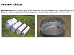
Innenmanschetten sind Elastomerprofile, die mit Spannringen im Kanal fixiert werden, oder Edelstahlhülsen, die mittels Elastomeren abgedichtet oder durch Reaktionsharze mit der Kanalwandung verklebt werden [ATVDVWKM143-7]. |
(Bild: Stuttgarter Hülse - Übersicht Manschetten V2A im Tunnelprofil) |
(Bild: Überlappung und vorgespannte Innenmanschette (Quick-Lock-V4A-verfahren)) |
|
|
|
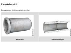
Einsatzbereiche der Innenmanschetten sind: | | (Bild: Einzelrohre)
Einzelrohre | (Bild: Rohrverbindungen)
Rohrverbindungen |
|
|
|
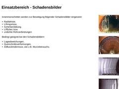
Innenmanschetten werden zur Beseitigung folgender Schadensbilder eingesetzt: - Radialrisse,
- Längsrisse,
- Scherbenbildung,
- Löcher, bzw.
- undichte Rohrverbindungen
Bedingt geeignet bei den Schadensbildern: - Lageabweichungen,
- Querschnittsverformungen,
- Abflusshindernisse, wie z.B. Wurzeleinwuchs.
| |
(Bild: Wurzeleinwuchs im Bereich einer Rohrverbindung #literature( '0000009687'))
|
|
(Bild: Scherbenbildung in einem Steinzeugrohr)
|
|
(Bild: Bruch der PE-Rohrwandung)
|
|
|
|
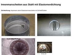
Dichtwirkung: Anpressen einer Elastomermanschette mit Dichtwülsten | |
(Bild: Überlappung und vorgespannte Innenmanschette (Quick-Lock-V4A-verfahren))
|
(Bild: Blick auf die Dichtwülste einer eingebauten Innenmanschette aus Stahl)
|
| |
(Bild: Fertig montierten Innenmanschette im Kanal)
|
(Video: Einbau der Innnenmanschette [FI-Rausc])
|
|
|
|
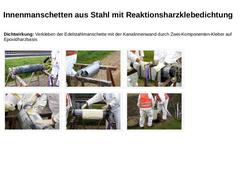
Dichtwirkung: Verkleben der Edelstahlmanschette mit der Kanalinnenwand durch Zwei-Komponenten-Kleber auf Epoxidharzbasis | |
(Bild: Aufgebockter Packer)
|
(Bild: Vorbereitung der Manschette - Packer mit aufgelegter Manschette)
|
(Bild: Vorbereitung der Manschette - Endgültiges Fixieren der Manschette mittels Klebeband)
|
|
(Bild: Vorbereitung der Manschette - Auftragen des Harzes auf den später überlappenden Teil der Manschette)
|
(Bild: Vorbereitung der … |
|
|
|
|
(Bild: Plus/Minus) |
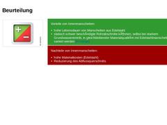
Vorteile von Innenmanschetten: -
hohe Lebensdauer von Manschetten aus Edelstahl
-
statisch schwer beschädigte Rohrabschnitte können, selbst bei starkem Grundwassereintritt, in gleichbleibender Materialqualität mit Edelstahlmanschetten saniert werden [FI-Geige]
|
|
Nachteile von Innenmanschetten: -
hohe Materialkosten (Edelstahl)
-
Reduzierung des Abflussquerschnitts
|
|
|
|
