|

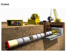
| (Image: Presentation of a pipe jacking with an intermediate jacking station)
|
|
|

|
In this method, jacking pipes are jacked by pressing-in through the subsoil from a starting shaft to a target shaft with the aid of a jacking station as well as intermediate jacking stations.
Jacking in a straight or curved line path is made possible by means of a steerable shield machine positioned at the head of the first pipe. The spoil excavated at the working face is conveyed to the surface through the jacked pipe string. | |
|
|

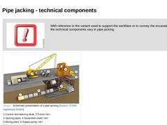
| (Image: Attention!) With reference to the variant used to support the workface or to convey the excavated soil the technical components vary in pipe jacking. | | (Image: Schematic presentation of a pipe jacking) |
|
|

|
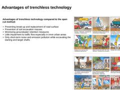
Advantages of trenchless technology compared to the open cut method: - Preventing break-up and replacement of road surface
- Prevention of soil excavation masses
- Minimizing groundwater retention measures
- Little impairment to traffic flow especially in inner urban areas
- Only short-term noise and emission pollution while excavating the starting and target shafts
| |
(Image: Disadvantages of the open cut method for installing drains and sewers (Part 1) [GSTT])
|
|
|
|

|
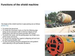
The duties of the shield machine in pipe jacking are
as follows [Scher77a] : - To protect the personnel,
- To create the necessary cavity so that the following pipe string can be pressed in with a minimum degree of soil deformation and with the lowest possible skin friction,
- To protect the cavity until the jacking pipes can finally carry all the loads and forces,
- To secure the working face against collapsing soil and rock as well as groundwater, and
…
|
|
|

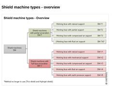
| (Image: Overview of shield machine types)
|
|
|

| In jacking processes, extensive and irreparable damages are frequently observed, which is due to irregularities of the subsoil. Although extensive subsoil investigations can reduce the subsoil risk, failures and damages cannot completely be excluded. | | (Image: Attention!) | These are the consequences of damages during pipe jacking: - Insufficient quality of the construction execution
- Delay
- High costs
- Environmental impacts
|
|
|
|

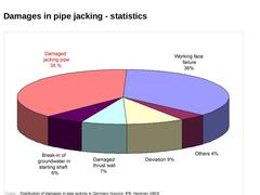
| (Image: Distribution of damages in pipe jacking in Germany (source: IFB, Hanover 1993))
|
|

|

|
|
This course includes tutorial services and a final examination. The installation of supply and disposal lines is still mostly performed using the open cut method consisting of digging a trench, laying the pipe under the protection of shoring, and subsequently backfilling the trench. Given the many disadvantages associated with this method along with the growing environmental awareness of the population, it is imperative that trenchless technologies be taken more strongly into account in the planning and construction of pipelines and utility networks. The learning module "Utility tunnelling" is divided into seven lessons, each focusing on a specific topic. The contents of the individual lessons are complemented with a link to more detailed literature. This literature is not relevant to the exam, but serves as a reference for a more in depth look.
The module "Utility Tunnelling" ends with a final examination, which references all of the modules content. In order to complete the course successfully, and stress-free within four weeks, we recommend following the following agenda which distributes the different modules evenly over the entire period: 1st week: Module: Introduction, Fundamentals and geotechnical investigations, Pipe jacking (Part 1)
2nd week: Module: Pipe jacking (Part 2), Microtunnelling
3rd week: Module: Jacking pipes, Jacking steering
4th week: Module: Starting and target shafts, Final exam
This schedule is only a recommendation, as it is of course up to you when and how you work through the curriculum. |
|
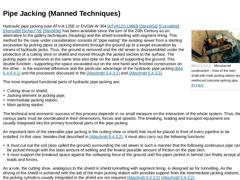
(Image: Microtunnel construction - View of the start shaft with main jacking station and reinforced concrete jacking pipe [FI-FBS]) Hydraulic pipe jacking (see ATV-A 125E or DVGW-W 304 [ATVA125:1996]) [Stein85a] [Conra84b] [Hornu89] [Scher77b] [Stein85e] has been available since the turn of the 20th Century as an alternative to the gallery techniques (heading) and the shield tunnelling with segment lining. This method for the case under consideration … |
|
Today, supply and discharge lines are still predominantly installed by using the open-cut method: a trench is dug, the lines are installed. Under the protection of an embankment or sheeting and the trench is filled afterwards. In the face of the numerous disadvantages as well as the citizens' growing environmental consciousness in the future it is urgently necessary to take trenchless technology into account much stronger than until today as an alternative … |
|

|
(Image: Simple hand shield - working face with natural support) |
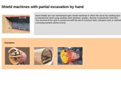
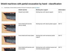
Hand shields are non-mechanised open shield machines in which the soil at the working face is loosened by hand using auxiliary tools (pickaxe, spades, shovels or pneumatic hammer). The removal of the spoil is carried out with the aid of conveyor belts, transport carts or tracked conveying buckets (dump trucks). |
|
|
|
Examples: |
(Image: Hand shield (external diameter 4672) with working … |
|
|
|
|
(Table: Classification of hand shields according to the type of working face support) |
|
|
|
(Image: Attention!)
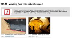
Natural support of the working face is always applicable when the existing subsoil is free of groundwater and the working face is a priori stable (working face without support) or is sufficiently supported by a self-forming earth wedge with a natural slope angle. |
|
(Image: Simple hand shield - working face with natural support) (Image: Handshield - working face with natural support) |
|
|

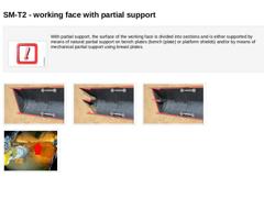
(Image: Attention!)With partial support, the surface of the working face is divided into sections and is either supported by means of natural partial support on bench plates (bench (plate) or platform shields) and/or by means of mechanical partial support using breast plates. (Image: Hand shield with breast plates - working face with mechanical partial support) (Image: Hand shield with benches (Bench shield) - working face with natural partial support) (… |

|
|
(Image: Attention!)
Shield machines with partial excavation by hand are predominantly used for: -
short jacking distances under 50 m
-
crossings of traffic ways
-
jacking of an extraordinary cross-section
-
groundwater-free soil or rock
|
|

|
|
SM-T1 - areas of application: -
stable, cohesive soil, i.e. firm-stiff and very stiff cohesive soil (soil class LBM 2 and 3 and/or LBO 2 and 3 according to DIN 18319) with a compressive strength of approx. 1.0 N/mm2
-
Rock with uniaxial compressive strength ≥ 5 N/mm2 (classes FD 2 to 4 and/or FZ 2 to 4)
|
SM-T2 - areas of application: -
loose to densely compacted non-cohesive soil (classes LNE 1 to 3 and/or LNW 1 to 3) with a particle size concentration < …
|
|
|

|
|
|
(Image: Shield with fixed intalled excavation machine - working face with natural support (SM-T1)) |
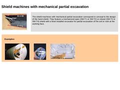
The shield machines with mechanical partial excavation correspond in concept to the design of the hand shield. They feature a mechanized open (SM-T1 or SM-T2) or closed (SM-T3 or SM-T4) shield with a fixed installed excavator for partial excavation of the soil or rock at the working face. |
|
|
|
Examples: |
(Image: Principles of support for open shield … |
|
|
|
|
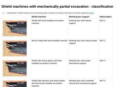
(Table: Classification of shield machines with mechanically partial excavation according to their type of work face support ) |
|
|
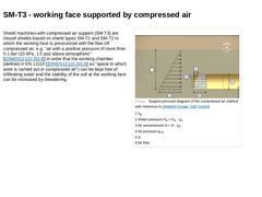
Shield machines with compressed air support (SM-T3) are closed shields based on shield types SM-T1 and SM-T2 in which the working face is pressurized with the flow off compressed air, e.g. "air with a positive pressure of more than 0.1 bar (10 kPa, 1.5 psi) above atmospheric" [ [DINEN12110:2014]] in order that the working chamber (defined in EN 12110 [ [DINEN12110:2014]] as "space in which work is carried out in compressed air") can be kept free … |

|
|
Working chamber:
Space in which work in compressed air is carried out.
[ [DINEN12110:2014]]
Air lock:
Pressure vessel with one or more chambers with access doors, which can be sealed and pressurized with compressed air.
[ [DINEN12110:2014]]
Material lock:
Air lock through which only material or equipment goes into or out of the working chamber.
[ [DINEN12110:2014]]
Personnel lock:
Air lock through which only persons go into or out of the working chamber. |
|
|
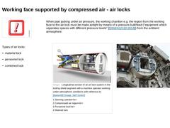
When pipe jacking under air pressure, the working chamber e.g. the region from the working face to the air lock must be made airtight by means of a pressure bulkhead ("equipment which separates spaces with different pressure levels" [ [DINEN12110:2014]]) from the ambient atmosphere. Types of air locks: -
material lock
-
personnel lock
-
combined lock
(Image: Longitudinal section of an air lock system in the trailing shield segment with … |
|

|
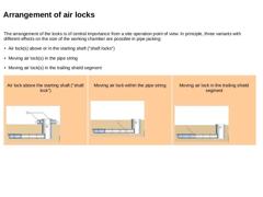
The arrangement of the locks is of central importance from a site operation point of view. In principle, three variants with different effects on the size of the working chamber are possible in pipe jacking: -
Air lock(s) above or in the starting shaft ("shaft locks")
-
Moving air lock(s) in the pipe string
-
Moving air lock(s) in the trailing shield segment
|
|
Air lock above the starting shaft ("shaft lock") (Image: Principle possibilities of arranging … |
|