|
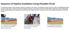
For efficient pumping, some granular material is needed in the mixture. The ballast can also serve as a dam for backfilling individual sections of the pipe, in which case the dam height should be in accordance with the final fill height. Placement of the hydraulically bound backfill material in the liquid form, directly from the ready mix truck, ensures an even and complete embedment of the pipe section. (Image: Placement of the unshrinkable fill … |
|
|
|
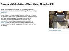
When using hydraulically bound backfill material in utility trenches, the structural calculation can be performed on as per [ATVA127]. In the process, the stiffness and strength values for the cover fill above the pipe crown, and the embedment at the side of the pipe have to be tested and verified by the respective manufacturer, based on mechanical suitability tests. Afterwards, input values for the calculation according to [ATVA127] can be determined … |
|
|
|
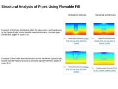
Vertical soil stresses |
Horizontal soil stresses |
|
Example of the load distribution after the placement, and hardening, of the hydraulically bound backfill material around a concrete pipe DN/ID 600, depth of cover 2 m. |
(Image: Vertical soil stresses) |
(Image: Horizontal soil stresses) |
|
Example of the traffic load distribution on the hardened hydraulically bound backfill material around a concrete pipe DN/ID 600, depth of cover 2 m. |
(Image: Vertical … |
|
|
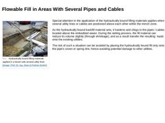
(Image: Hydraulically bound filling materials applied in a trench with several utility lines) Special attention in the application of the hydraulically bound filling materials applies when several utility lines or cables are positioned above each other within the trench zone. As the hydraulically bound backfill material sets, it hardens and clings to the pipes / cables located above the embedded sewer. During the setting process, the fill material … |
|
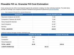
Costs savings are one of the most important aspects the contractor is looking for when selecting materials. The table below provides an average cost comparison between flowable fill and granular fill placement [[VancePool2008]]. (Table: Flowable fill vs. granular fill cost) |

|
(Image: Seitenverfuellung Einsparpotential Fluessigboden DN 350 - DN 700) Practical Example: Possible cost savings through the use of hydraulically bound backfill material (Image: Seitenverfuellung Einsparpotential Fluessigboden >DN 1200) DN 600 with base Backfilling cost using flowable fill: 0.7 m³ / m x 45.00 € / m³ = 31.50 € / m a) Excavated soil reused for backfilling |
Depth of excavation |
Cost of conventional backfilling |
Excavation savings |
|---|
|
T = … |
|
|
Various advantages make the use of hydraulically bound backfill materials a good alternative to the conventional backfilling of utility trenches with granular, unbound back-fill material: -
Prevention of typical installation errors/damage causes that can occur during the conventional installation procedure (e.g. insufficient backfilling and compaction in the spaces either side of the pipe, point loading of the pipe etc.)
-
Reduction of the trench widths …
|
|
-
Reduction of the construction time
-
Prevention of surface settlings (particularly in the area of the usual shoring gap)
-
No need for mechanical compaction, hence no vibrations. Reduction of noise and vibration emissions
-
Prolongation of the operating life of the piping (reduction of ex-/infiltrations due to a certain redundancy, prevention of root ingrow, defined bedding conditions because of a prevention of typical installation errors/causes of …
|

|
It should be noted that (if at all possible) the use in utility trenches with a steep gradient (> 10 %) requires special equipment. In the case of a practical application, expert consulting engineers should be requested to determine the precise requirements for the individual case (general, mechanical/structural, chemical, thermal etc.), as well as to carry out the required analyses for a verification of the serviceability, provided that these have … |
|
|

|
|
|
The optimised installation method belongs to the open cut method of construction, i.e. the installation of sewers by the excavation of a trench, the installation of pipes protected by sloping or lining of the walls, and the subsequent backfilling of the trench. When using the optimised installation method, the already introduced specifications need to be followed, provided that the particularities of this method of installation allow for deviations. |
|
The essential differences of the optimised installation method in comparison to the traditional way of sewer installation by use of the open trench are: -
The use of special optimised concrete pipes
-
No necessary working space at the sides of the pipe
-
The use of a special linear type of lining
-
The installation and connection of the pipes by means of a special installation system
-
The backfilling of the embedment areas between the pipe and the in …
|
|
Criteria to be taken into account with regard to pipe design: -
Prevention of installation-related damages
-
Simplified requirements for the installation of piping
-
Suitability for automated installation
-
Optimisation of the structural characteristics
-
Beneficial interrelation between pipe weight and load bearing capacity
|
|
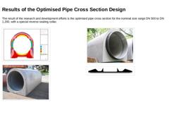
The result of the research and development efforts is the optimised pipe cross section for the nominal size range DN 500 to DN 1,200, with a special reverse sealing collar. (Image: Optimisation of the pipe shape by means of FEM analyses) (Image: Optimised pipe) (Image: Optimised pipe with reverse sealing gasket) (Image: Detailed view: Cross section of the reverse sealing element) |
|
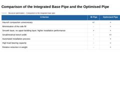
(Table: Structural optimisation – Comparison to the integrated base pipe) |
|
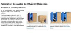
Reduction of the excavated quantity of soil (Image: Comparison of the traditional and the optimised installation method) (Image: Optimised installation: About 75% less excavated soil owing to a small trench) As the working space is no longer required, the trench width can be significantly reduced. Compared to the “traditional” open cut method of construction, a considerably smaller quantity of soil has to be excavated (for DN 700 about 25%), so that … |
|
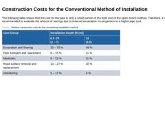
The following table shows that the cost for the pipe is only a small portion of the total cost of the open trench method. Therefore, it is recommended to evaluate the amount of savings due to reduced excavation in comparison to a higher pipe cost. (Table: Relative construction costs for the conventional installation method) |
|
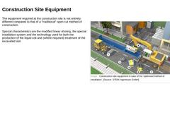
(Image: Construction site equipment in case of the “optimised method of installation”) The equipment required at the construction site is not entirely different compared to that of a "traditional" open cut method of construction. Special characteristics are the modified linear shoring, the special installation system and the technology used for both the production of the flowable fill and (where required) treatment of the excavated soil. |
|
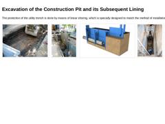
The protection of the utility trench is done by means of linear shoring, which is specially designed to match the method of installation. (Image: Initial excavation for the optimised method of installation) (Image: Insertion of the outer panels for the optimised method of installation) (Image: Insertion of the panel soldiers and outer panels for the optimised method of installation) (Image: Re-positioning of the panel soldiers (U-boogie car) for the … |
|
|
(Image: Creation of the lower bedding layer) |
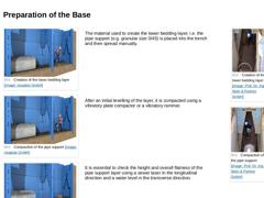
The material used to create the lower bedding layer, i.e. the pipe support (e.g. granular size 0/45) is placed into the trench and then spread manually. |
(Image: Creation of the lower bedding layer) (Image: Compaction of the pipe support) |
|
(Image: Compaction of the pipe support) |
After an initial levelling of the layer, it is compacted using a vibratory plate compactor or a vibratory tamper. |
|
(Image: … |
|
|
|
(Image: Securing device for the optimised pipe) |
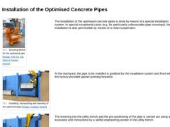
The installation of the optimised concrete pipes is done by means of an excavator mounted pipe installation system. In special exceptional cases (e.g. for particularly unfavourable pipe crossings), the installation is also permissible by means of a chain suspension. |
(Image: Grabbing, transporting and lowering of the optimised pipe) |
At the stockyard, the pipe to be installed is grabbed by the installation … |
|
|
|
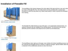
(Image: Formwork to close the infill areas for liquid soil) |
The backfilling of the spaces between the outer edge of the pipe and the in situ soil is done by means of flowable fill. Thus, the utility trench is to be provided with a section-wise formwork to close the infill areas (e.g. sheet metal board) in order to prevent the flowable fill from leaking. |
|
(Image: Insertion of liquid soil) |
The flowable fill is filled directly on top of the pipe, … |
|
|
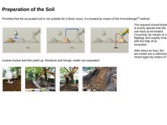
Provided that the excavated soil is not suitable for a direct reuse, it is treated by means of the Kronenberger® method: (Image: Dosing of the mixed binder) (Image: Pre-mixing and mixing by means of a crusher bucket) (Image: Separation of residues and foreign matter) The required mixed binder is evenly spread onto the soil mass to be treated (“covering” by means of a BigBag) and roughly mixed with the help of an excavator mounted mixing unit and/or … |