|
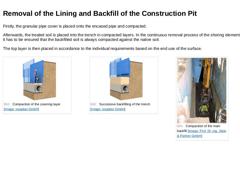
Firstly, the granular pipe cover is placed onto the encased pipe and compacted. Afterwards, the treated soil is placed into the trench in compacted layers. In the continuous removal process of the shoring elements it has to be ensured that the backfilled soil is always compacted against the native soil. The top layer is then placed in accordance to the individual requirements based on the end use of the surface. |
(Image: Compaction of the covering layer) |
|
|
|
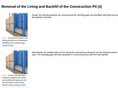
(Image: Removal of the girders and shoring elements and simultaneous backfilling of the cavities) |
Finally, the shoring elements are removed and the resulting gaps are backfilled with flowable fill via the injection channels. |
|
(Image: In case of the optimised method of installation the cavities are backfilled with liquid soil in the removal process of the shoring elemets) |
Alternatively, for suitable types of soil, the braces and shoring elements … |
|

|
-
Avoidance of the typical installation errors through the optimisation of the pipe shape, as well as the implementation of a partly automated installation method.
-
Lower quantity of excavated soil as a result of a smaller trench width
-
Lower volume of waste material to be dumped on landfill sites as the excavated material is reused
Conclusion: The optimised method of installation represents a more efficient, more environmentally sound, and less damage-… |

|
|

|
|

|
A compaction test (i.e. of the soil-mechanical parameters of the material that has been backfilled into the embedment, and used in the main backfill) is required in order to verify the load assumptions that have been made in the planning stage, or to adjust them based on changing conditions and thus, to assert that the soil-mechanical parameters of the piping comply with the requirements that have been determined in structural calculations. Furthermore, … |

|
A compaction test of the bedding layer is of particular importance, as this layer has to bear loads before the side fill, cover and main backfill are placed and compacted. Thus, a compaction test at an earlier point in time is highly recommended over a compaction test after the completion of the construction works. This ensures that subsequent settlings or subsidence can be minimised or even prevented. |

|
In order to prevent gross defects or deficiencies in the construction work and contractual debates on the evaluation of results obtained by means of different test methods and testing devices, it should be proceeded as follows (provided that nothing else is specified in the contract): |

|
-
If an agreement on the check test results cannot be achieved, direct test methods should be used for the compaction test.
-
If, due to the characteristics of the different types of soil, the test methodology of direct methods is either too difficult or too time-consuming, or if direct test methods cannot be carried to the required extent due to the progress of the construction work, indirect test methods based on either verifiable rules of thumb …
|

|
The photos below summarise the currently available compaction test methods. In the following, their fields of application will be illustrated. (Image: Core Cutter Method) (Image: Replacement Test) (Image: Dynamic Plate Load Test) (Image: Dynamic Probing) |

|
|
(Image: Core Cutter Method) |
The core cutter method is only suitable for fine types of soil (clays and silts) without any noteworthy coarse particle percentages as well as for (fine to medium) sands. The core cutter method is particularly suitable for cohesive types of soil with a firm consistency and medium-densely packed fine sands. |
|

|
|
(Image: Replacement Test) |
The sand replacement test can be used productively in cohesive and non-uniformly grained or coarse, non-cohesive types of soil, into which a core cutter cannot be inserted without affecting the soil fabric (fine to medium types of sand, gravel-sand mixtures). In types of soil with particles larger than that of coarse gravel (63 mm) or with pore spaces large enough to be penetrated by the test sand, the sand replacement … |
|

|
|
(Image: Dynamic Plate Load Test) |
The dynamic plate load test can be used in layers of soil with a dynamic modulus of deformation of EVd = 15 MN / m2 to 70 MN / m2. It is preferably suitable for mixed- and coarse particle, non-cohesive types of soil with a largest particle size of ≤ 63 mm. Provided that the material under test does not change and the tests are correlative, the dynamic plate load test by means of the so-called light drop weight device … |
|

|
|
(Image: Dynamic Probing) |
The most common test method for checking the degree of compaction in situ is the dynamic probing method. This method has the advantage of being able to test even at great depths (depending on the testing device in use up to 40 m), provided that the back-filled soil does not include any larger stones, as they would form obstacles during testing. |
|

|
(Table: Common errors and consequences of faulty compaction testing) |

|
(Table: Common errors and consequences of faulty compaction testing (2)) |

|
|

|
Congratulations! You have successfully finished this module. Next, you will have the opportunity to review the newly acquired knowledge with an interactive questionnaire. You can, of course, still navigate back to any point in the modules if you wish to review a specific point or subject. Stay curious! |

|
The installation of water and wastewater networks is carried out around the world to a large extent in open cut construction. This module focuses on all of the relevant information relating installation and alignment of the pipes, backfill compaction, alternative backfill materials, and the removal of the shoring. Upon the successful completion of this module, you will be able to: - identify and apply the main rules and regulations,
- ensure a high quality of workmanship on site,
- identify and assess construction errors, and
- optimise the installation process.
|

|
According to EN 13331-1 [DINEN13331-1a] [DINEN13331-2], trench lining system is understood to be a construction of prefabricated components that are used for support of vertical excavation walls. The main load-bearing elements are panels, slide rails and support components. In the application case at hand, the following trench lining systems are used in the open cut method of construction [DINEN13331] : - Edge-supported trench lining system (ES type): "…
|
|
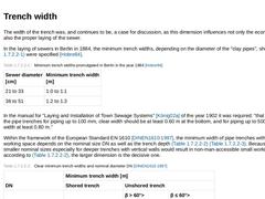
The width of the trench was, and continues to be, a case for discussion, as this dimension influences not only the economics but also the proper laying of the sewer. In the laying of sewers in Berlin in 1884, the minimum trench widths, depending on the diameter of the "clay pipes", shown in Tabelle 1.6.1.1 were specified [Hobre84]. (Table: Minimum trench widths promulgated in Berlin in the year 1884 [Hobre84]) In the manual for "Laying and Installation … |
|
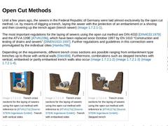
(Image: Laying a sewer unsing the open cut method [FI-Emun]) Until a few years ago, the sewers in the Federal Republic of Germany were laid almost exclusively by the open cut method, i.e. by means of digging a trench, laying the sewer with the protection of an embankment or a shoring and then covering up the trench again (trench sewer) (Bild 1.6.1). The most important regulations for the laying of sewers using the open cut method are DIN 4033 [DIN4033:… |

|
(Image: Requirements for the installation of sewers in open trench - Background image shows an unprofessional installation of a sewer in open trench - Requirements are not met) (Image: Requirements for the installation of sewers in open trench - Background image shows an unprofessional installation of a sewer in open trench - Requirements are not met - Image 2) The goal is to construct pipelines in such a way that the risks associated with the transportation … |

|
The installation method (jetting, insertion into boreholes, etc.) for the well-points is highly dependent on the subsoil conditions. The pictures show well-points in the form of self-jetting well-point. The self-jetting well-points are installed using high-pressure water supplied to the top of the riser pipe from a water jetting pump. At the tip of the self-jetting well-point below the wellpoint screen, there is a hollow jetting shoe. Near the lower … |
|
Feb 19, 2013
News
Achim Kühn
With Pipe Express® the Herrenknecht AG has developed a new semi-trenchless method for installing pipelines. In comparison with the open construction method, routes are considerably narrower, no groundwater lowering is necessary and there is less impact on nature. This has a very positive effect on the grid operators' construction costs.
|