
|
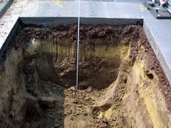
An extraction of samples via sampling devices is ”a process in which samples are extracted by means of sampling devices from trial pits, investigation pits and investigation galleries or from the borehole at chosen depth levels” [ENISO22475:2007]. In the case at hand, samples are mostly taken in a trial pit. (Image: Schematic outline of a subsurface exploration) (Image: Presentation of the results of the extended subsoil investigation) (Image: Exploration) (… |

|
The extraction of block samples is done by cutting a sample from the soil or rock using special methods. In the given case of application this type of sampling is unlikely to be relevant. |

|
|

|
Indirect explorations are explorations that allow for conclusions about the subsurface by a given correlation between physical indicators and soil- or rock-mechanical parameters. Indirect explorations include: The results of measurement gained from this exploration method cannot be attributed directly to the subsurface parameters, but have to be compared … |
|
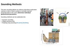
The term sounding defines an indirect subsurface exploration method in soils in which a probe is normally inserted perpendicularly to the soil to determine individual geotechnical parameters. Sounding methods can be subdivided into -
Dynamic sounding,
-
(Static) pressure and
-
Rotating wing sounding [Reute92] [Weiß96a].
(Image: Application of a dynamic probe in situ) (Image: Schematic principle of a rotating wing probe) (Image: Schematic depiction of … |

|
Depending on the device that is used, a probe is driven (standard penetration test / dynamic probing) or pushed (cone penetration test) into the subsoil or turned around its longitudinal axis at a specific depth (vane shear test). From the penetration resistance (sounding resistance) - that has to be defined individually - and its change with increasing depth, conclusions can be drawn for example about a layer’s strength or the degree of compaction, … |
|
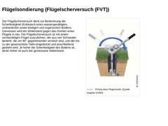
The vane shear test serves to determine the shear strength (cohesion) of a water-saturated, undrained as well as cohesive and organic soil. The resistance against the rotation of a vane wing is measured in situ. The vane shear test is carried out with a rectangular vane consisting of four blades offset by 90° to each other, which is pressed in to the desired depth and then rotated. The higher the shear strength of the soil, the higher the measured … |
|
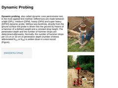
Dynamic probing, also called dynamic cone pentrometer test, is the most applied test method. Differences are made between a light (DPL), medium (DPM), heavy (DPH) and super heavy (DPSH) dynamic probe. Without any borehole, directly from the ground surface the probe is driven into the ground by means of a hammer of a defined weight and a constant drop height. The penetration depth and the number of hammer drops are determined afterwards. Normally, … |
|
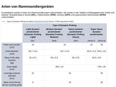
Basically 4 types of dynamic probing are distinguished. In the table, they are divided into light (DPL), medium (DPM), heavy (DPH) and super-heavy (DPSH) penetration probes depending on their size and other characteristics. (Table: Types of Dynamic Probing) |

|
The following points must be taken into account when evaluating number of blows: -
The test type;
-
A precise description of the method;
-
The groundwater conditions;
-
The influence of the overburden pressure;
-
The type of subsoil, especially whether stones or coarse gravel influence it.
|
|
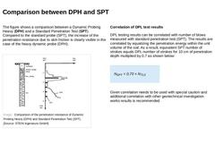
The figure shows a comparison between a Dynamic Probing Heavy (DPH) and a Standard Penetration Test (SPT). Compared to the standard probe (SPT), the increase of the penetration resistance due to skin friction is clearly visible in the case of the heavy dynamic probe (DPH). (Image: Comparison of the penetration resistance of Dynamic Probing Heavy (DPH) and Standard Penetration Test (SPT)) Correlation of DPL test results DPL testing results can be correlated … |
|
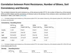
The correlation between the point resistance qcs of the pressure probe CPT-E, the number of blows N10 of the dynamic probes DPL, DPM and DPH (Table) and the consistency of cohesive soils or the density of non-cohesive soils in accordance with Placzek is illustrated in Table 1 and Table 2 [Placz85]. (Table: Correlation between point resistance qc of the pressure probe CPT-E, the number of blows N10 of the dynamic probes DPL, DPM, DPH and the consistency … |
|
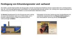
For reasons of economic efficiency, the composition and the characteristics of the subsoil and the groundwater conditions can only be tested at a number of selected locations, particularly in the case of linear structures (such as supply and drainage pipes). As an example, the geotechnical investigation can be omitted in the case of a pipe replacement using a bursting method via short distances and in artificially backfilled soil. (Image: Bursting … |

|
|
|
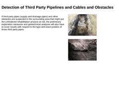
If third party pipes (supply and drainage pipes) and other obstacles are suspected in the surrounding area that might put the unhindered rehabilitation process at risk, the preliminary exploration measures and geotechnical analyses will also have to cover results with respect to the type and exact position of those third party pipes. (Image: Preliminary Exploration Measure - Search Slot Bild 1) (Image: Preliminary exploration measure - Search slot … |

|
The following approach has proven to be useful in seeking information: -
Enquiries at public utility companies, civil engineering offices or drainage departments/companies, telecommunication companies, energy-, gas- and water suppliers and other utility and waste removal services.
-
If there are no plans available, ask for a written confirmation that explicitly states the absence of third party pipes in the area of the lines and manholes under rehabilitation.
|
|
|
|
This module teaches the basics of geotechnical investigations for civil engineering purposes. The described subsoil investigation by indirect (e.g., drilling methods) and direct exploration methods (e.g., dynamic sounding) form the basis for an understanding of a civil engineering description and evaluation of soil and rock. After completing this module, you will have a sound knowledge of: - The objective of a geotechnical investigation;
- The purpose of structural and subsoil investigation by means of excavations;
- Differentiation between direct and indirect excavation methods, such as drilling methods and indirect excavation methods, such as dynamic sounding.
|
|
The documentation of damages, defects, other peculiarities (findings) in sewers and pipes within the scope of CCTV inspection is not possible without a uniform nomenclature. In Europe, EN 13508 Part 2: "Coding system for visual inspection" provides the normative basis for documenting and describing various findings, which later serve the engineer as a basis for assessment.
This module provides the basic knowledge required for the structure and application of the coding system. After completing this module, you will have a sound knowledge of: - coding system according to EN 13508-2;
- differentiation between basic information and findings;
- differences in the coding system between sewers and manholes;
- codes for route finding, tightness indication, location on the circumference and
- procedure of inspection in an object.
Duration:
2,5 h |

|
|

|
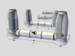
European coding systems define the term defect as „a structural, environmental or hydraulic condition that causes or is expected to cause an unacceptable impairment of functionality with regard to use. “ [ATVM143-1:2004]. The following explanations refer primarily to structural defects, hereinafter also referred to as damage. These damages can also be of importance when assessing the hydraulic performance and the impact on the environment, but also … |
|
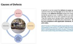
(Image: Diagram - Causes of Defects) In general, it can be stated that defects in sewer systems are caused on the one hand by age and on the other hand by changes in the different stresses acting from outside or inside during the period of use. In addition, there is so-called initial damage, which can occur over a period of up to several years. They are mainly due to design and/or material defects and/or incorrect selection of materials and components - |
|
Important: Knowledge of the defects, their manifestations, causes and consequences is one of the most important prerequisites for the optimal planning and design of integral solutions to meet the performance requirements - and here in particular for the selection of suitable procedures for the structural solution. The following explanations refer primarily to structural defects, hereinafter also referred to as damage. These damages … |

|
A coding system consists of codes for basic information and individual observations, whereby the codes for individual observations within the sewers and drains are to be binding. Observations are understood to mean defects and condition characteristics, and header information refers to a pipeline as a whole. It is recommended to adopt the binding codes of EN 13508-2 as completely as possible. In justified individual cases, restrictions may be proposed. |

|
|