|
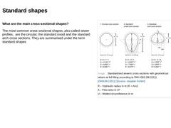
What are the main cross-sectional shapes? The most common cross sectional shapes, also called sewer profiles, are the circular, the standard ovoid and the standard arch cross sections. They are summarised under the term standard shapes (Image: Standardised sewers cross sections with geometrical values at full filling according to DIN 4263 (06.2011)) |
|
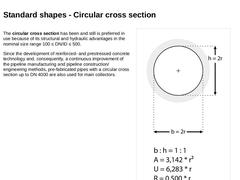
The circular cross section has been and still is preferred in use because of its structural and hydraulic advantages in the nominal size range 100 ≤ DN/ID ≤ 500. Since the development of reinforced- and prestressed concrete technology and, consequently, a continuous improvement of the pipeline manufacturing and pipeline construction/engineering methods, pre-fabricated pipes with a circular cross section up to DN 4000 are also used for main collectors. |
|
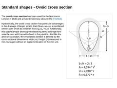
The ovoid cross section has been used for the first time in London in 1846 and arrived in Germany about 1870 [Frühl10]. Hydraulically, the ovoid cross section has particular advantages in the drainage of larger, erratic drain flows, as e.g. in combined sewers with small dry weather flows Qt/Qv =0.22. Additionally, this special shape allows great cleansing effect and high flow velocity even with low water level in the pipeline. Just like the arch cross … |
|
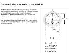
Arch cross sections offer advantages for large flows and a restricted construction height. Although the hydraulic efficiency for partial filling is poor, yet the shape is structurally advantageous because it approximates the course of the pressure line. In the past, two more cross sectional shapes have been in use that have been derived from the standard arch cross section, namely the “extended arch cross section” and the “squashed arch cross section”. |
|
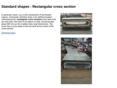
In particular cases, e.g. in the construction of stormwater sewers, stormwater retention tanks or for defined location collecting points, rectangular cross sections have been and are still used. DIN 4263 in its edition of 1991 recommended about 800 mm as the smallest clear axial dimensions. The invert has a cross-slope to the low point at the centre of the cross-section. [DIN4263:2011] (Image: Rectangular cross section - profile) (Image: Reinforced … |
|
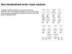
In addition to these standard cross sections there are numerous other cross sectional shapes and -sizes, that, partly, have also been standardised in the past and that are still used today in individual cases. Examples for non-standardised cross sections in practice: (Image: Non-standardised sewer cross section - Parabolic cross section made of masonry) (Image: Non-standardised sewer cross section - Channel cross section made of masonry) (Image: Non-… |
|
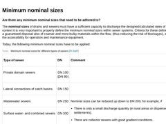
Are there any minimum nominal sizes that need to be adhered to? The nominal sizes of drains and sewers must have a sufficient capacity to discharge the designed/calculated rates of inflow. In this context it is very important to properly define the minimum nominal sizes within sewer systems. Criteria for these definitions could be a guaranteed disposal also of coarser and more bulky materials within the flow, (thus reducing the risk of blockages), … |
|
|
|
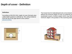
Definition: According to DIN EN 1610, depth of cover (formerly also called depth position) is defined as “the vertical distance from the top of the pipe barrel to the surface." [EN1610:2015] The lowest level of cellars/basements to be drained normally defines the minimum depth of cover of combined water and wastewater sewers. Another aspect which may influence the minimum depth is the position of the receiving water body. (Image: Depth of cover- vertical … |
|
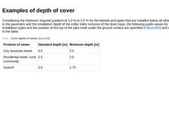
Considering the minimum required gradient of 1.0 % to 2.0 % for the laterals and pipes that are installed below all other supply lines in the pavement and the installation depth of the cellar inlets inclusive of the drain traps, the following guide values for the individual installation types and the position of the top of the pipe shaft under the ground surface are specified in [Busch65] and can be found in the table. (Table: Cover depths of sewers [… |
|
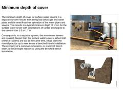
The minimum depth of cover for surface water sewers in a separate system results from being laid below gas and water pipes and the need frost-free operation of the water pipes and sewers. This results in a typical minimum depth of 1.5 m for the surface water sewer with connections of rainfall downpipes to the sewers from 1.5 to 1.7 m Consequently, in a separate system, the wastewater sewers are installed deeper than the surface water sewers. When … |

|
Definition: A gradient may be defined as fall divided by distance. GRADIENT = FALL / DISTANCE The invert gradient is defined as follows: Invert gradient: Inclination of the invert line of the sewer or drain (e.g. in ‰). Sewage is a mixture of water including various solids, among which there are also those that settle. Their sedimentation can be avoided in sewer systems that are operated as a gravity system, if the velocity of discharge is not permitted … |
|
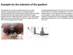
The gradient of a sewer in its total course up to a main collector, sewage treatment plant or pumping station is normally selected such that the upper sections with the smaller nominal sizes and the smaller flows are laid with a larger gradient than the middle and lower sections, as in these areas, larger and more constant flows, and thus, a larger wall shear stress of the sewage are very likely. Usually gradients between 3 ‰ and 10 ‰ are chosen in … |
|
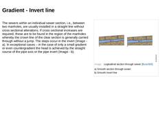
The sewers within an individual sewer section, i.e., between two manholes, are usually installed in a straight line without cross sectional alterations. If cross sectional increases are required, these are to be found in the region of the manholes whereby the crown line of the clear section is generally carried through without a jump. The steps occur in the invert (Image - a). In exceptional cases – in the case of only a small gradient or even countergradient … |

|
|
|
The selection of the appropriate pipe material for the construction or replacement of a sewer requires the design engineer to consider a variety of factors in order to meet the diverse functional requirements of a drain and sewer system. Important to note, there is no "universal" pipe material for each and every application. The design engineer should carefully considered the criteria for the selection of the pipe materials, listed below, based on … |
|
Other factors influencing the choice of material are: |
|
Which functions must be fulfilled and which dimensional requirements must be adhered to? -
Dimensions of pipes and fittings: The product standards must provide information on nominal sizes, diameters and tolerances, straightness, rectangularity of pipe end faces, pipe length and continuity of invert.
-
Roughness of pipe wall: Inside walls of pipes must be free of visible defects that may negatively affect their hydraulic performance.
|

|
|

|
Since the middle of the 19th century sewer systems have been constructed according to plan in Europe. The ancient Romans’ high standard of knowledge served as a basis for German sewer systems, as the Romans had constructed large brick sewers (Image ) and often used “clay pipes” for small nominal sizes that were cone-shaped at one end, so that the pipes could be inserted into each other and thus connected. For over a century, the accessible sewer systems … |
|
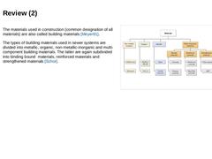
The materials used in construction (common designation of all materials) are also called building materials [Meyer81]. The types of building materials used in sewer systems are divided into metallic, organic, non-metallic-inorganic and multi-component building materials. The latter are again subdivided into binding bound materials, reinforced materials and strengthened materials [Schor]. (Image: Construction materials used in sewers [Stein01c]) |
|
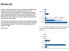
However, the greater part of sewers consists of prefabricated pipes of various materials, especially of concrete and reinforced concrete or vitrified clay. Plastic piping and pipes made of asbestos cement have been used since about 1930, pipes made of ductile cast iron since the second half of the 20th century, fibre cement since about 1990 and polymerised concrete since the 1980s. The distribution of materials in sewers in the Federal Republic of … |
|
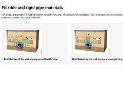
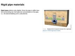
For pipes, a distinction is made between flexible (PVC, PE, PP, ductile iron, fiberglass, etc.) and rigid (clinker, vitrified clay, concrete, polymer concrete, etc.) pipe materials. (Image: Displacement of ground stresses for a flexible pipe) Redistribution of soil stresses in a flexible pipe and wide trench (after Leonhard) (Image: Displacement of ground stresses for a rigid pipe) Redistribution of soil stresses in a rigid pipe and wide trench (after … |
|
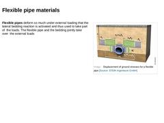
Flexible pipes deform so much under external loading that the lateral bedding reaction is activated and thus used to take part of the loads. The flexible pipe and the bedding jointly take over the external loads (Image: Displacement of ground stresses for a flexible pipe) |
|
Rigid pipes deform only slightly. Since the pipe is stiffer than the surrounding soil, the loads are concentrated on the pipe, i.e., the lateral bedding soil is unburdened. (Image: Displacement of ground stresses for a rigid pipe) |