
|
With jacking in cohesive soils, it must be assumed that the overcut closes again due to consolidation and creep processes in the soil so that, in the calculation of the pipe loading, it must not be taken into account. The determination of the load perpendicular to the pipe axis is carried out in this case analogous to Abschnitt 14.6.1.1. The external radius of the pipe must be used for the dimensions of the void expansion, e.g. of the soil displacement. |

|
(Image: Formation of the fracture bodies in the soil for soil displacement methods with overcut in non-cohesive soils [Falk97b]) The load assumptions to ATV-A 161E [ATVA161] apply in this case. With flexible pipes or pipe materials such as plastics or steel, an increase of the bedding reaction pressure resulting from the compaction of the soil in the immediate vicinity of the pipe with the result of an increase in the soil strength can be assumed. … |
|
|
|
Because of the overcut, the traversed cavity is, in many cases, stable in the construction condition so that the pulled, pushed or pressed in pipe is not subject to loading at the start. This temporary stability is improved in the soil displacement method in comparison to the soil removal method by means of: - The compaction of the soil in the vicinity of the pipe and the thus resulting soil properties
- The stress condition created by the expansion
- The …
|

|
|

|
|
|
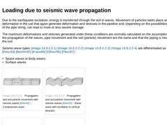
Due to the earthquake excitation, energy is transferred through the soil in waves. Movement of particles takes place and thus deformation in the soil that again generate deformation and stresses in the pipeline and, depending on the possibilities of movement of the pipe string, can lead to more or less severe damage. The maximum deformations and stresses generated under these conditions are normally calculated on the assumption that during the propagation … |
|
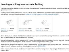
During an earthquake, fracturing can occur in the underground due to the displacements caused by ground surface faulting or other ground movements. Faulting (displacement of the seismic fracture surface) occurs in the form of relative horizontal displacement (strike-slip faults), normal faults or reverse faults (overthrust) (Bild 14.7.1.2) (Bild 14.7.1.2) (Bild 14.7.1.2). |
(Image: Faulting [Bachm95] - As horizontal displacement)
|
(Image: Faulting [… |
|

|
|
(Image: Typical PGD patterns in the longitudinal direction [ORour92])
|
|
(Image: Typical PGD patterns in the lateral direction [ORour92])
|
The greatest seismic danger to directly buried pipelines is the deformation induced locally by earthquakes (e.g. liquefaction, sliding) which are often called PGD (Permanent Ground Deformation). Liquefaction is understood in the following to be the loss of shear strength of the soil due to earthquake stimulation. … |
|
|
|
The failure of the pipelines is caused by the floating of the pipes due to soil fluidizing, rotation in the pipe joints, pulling out of the pipe joints or failure of the jacking pipes due to exceeding the acceptable stresses as well as failure of stability (buckling or kinking) of the pipeline. Which of these types of failure will occur depends on the type of the pipe joint. Pulling the pipe out of the pipe joint and its associated leakage problems … |
|
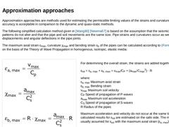
Approximation approaches are methods used for estimating the permissible limiting values of the strains and curvatures. Their accuracy is acceptable in comparison to the dynamic and quasi-static methods. The following simplified calculation method given in [Wang80] [Newma67] is based on the assumption that the seismic wave patterns do not alter and that the pipe and soil movements are the same size. Pipe strains and curvatures occur as well as relative … |
|
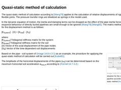
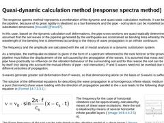
The quasi-static method of calculation according to [Wang79] applies to the calculation of relative displacements of rigid pipes with flexible joints. The pressure transfer rings are idealized as springs in the model used. In the dynamic equation of motion, the inertia and damping terms can be dropped as the effect of the pipe inertia forces on the response behaviour of directly buried pipelines are small enough to be ignored [Wang79] [Wang80]. The … |
|
The response spectra method represents a combination of the dynamic and quasi-static calculation methods. It can be used when the pipeline, because of its great rigidity is idealized as a bar framework and the pipe - soil system can be modelled by springs and substitution dimensions [Kraus84] [Flesc97]. In this case, based on the dynamic calculation soil deformations, the pipe cross sections are quasi-statically determined. Here it is assumed that … |
|
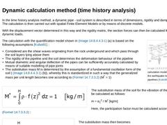
In the time history analysis method, a dynamic pipe - soil system is described in terms of dimensions, rigidity and damping matrixes. The calculation is then carried out with spatial Finite Element Models or by means of discrete models. With the displacement vector determined in this way and the rigidity matrix, the section forces can then be calculated from the dynamic loads. (Image: Dynamic calculation model for determining the earthquake loading … |

|
|
|
|
|
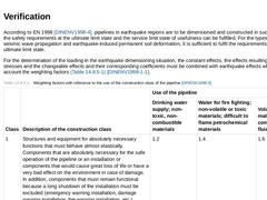
According to EN 1998 [DINENV1998-4], pipelines in earthquake regions are to be dimensioned and constructed in such a way that the safety requirements at the ultimate limit state and the service limit state of usefulness can be fulfilled. For the types of effects of seismic wave propagation and earthquake-induced permanent soil deformation, it is sufficient to fulfil the requirements at the ultimate limit state. For the determination of the loading … |

|
In the planning of pipeline or pipeline systems, regions with a high potential of earthquake damage should be circumnavigated as far as possible. This includes regions, for instance: - In or above saturated, sandy or silty soils
- Toes of slopes
- With active distortions (large displacements)
- With large changes of the relevant dynamic soil properties
- With strong morphological and geological discontinuities
If these regions cannot be circumnavigated, then … |
|
|

|
|
|
Advance subsidence or heaving occurs before the traversal of the jacking or shield machine due to the release of stress of the soil at the working face or as a result of incorrectly adjusted support pressure or bore head compacting pressure for stabilizing the working face (Abschnitt 14.2.1.1). The distance of the beginning soil deformation usually corresponds to a distance of 3 x the diameter of the jacking or shield machine ahead of the working … |

|
The subsidence above the jacking or shield machine occurs, if at all, due to deformations of the shield skin and can usually be ignored. In strongly changeable inhomogeneous soils with partly high loam portions, cases have become known in which soil deformations occurred due to the longitudinal movement of strongly adhesive soil materials attached to the shield skin. This causes subsequent partial sealing at concentrated points and high lateral pressures. … |
|
Trailing subsidence can occur, for instance, due to the annular gap created by the overcut, missing or poor annular gap filling, soil displacements caused by steering or curved paths, vibrations and the deformation of flexible jacking pipes [Jancs01]. There is very little trailing subsidence in pipe jacking as the overcut is very small and the deformability of the jacking pipes is very low (for rigid reinforced concrete pipes, the deformability is … |

|
|