|
|
|
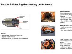
(Image: Selection of the nozzle and the jet angle) Nozzle: • Number and diameter of openings
• Type of nozzle inserts
• Jet deflection in the nozzle? (Pressure loss) (Image: Deposits sewer - mixtures of organic and mineral substances) Sewer channel
(Cleaning objectives): • nominal size, length, depth material
• structural condition
• quantity and type of deposits
• flow condition and level of backup. (Image: Combined high pressure flushing and suction … |

|
Congratulations! You have successfully finished this module. Next you will have the opportunity to review the newly acquired knowledge with an interactive questionnaire. You can of course still navigate back to any point in the modules if you wish to review a specific point or subject. Stay curious! |

|
|
|
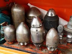
An essential part of high-pressure cleaning are the cleaning nozzles. This module covers the complex task of choosing the optimal cleaning nozzle for the respective application, as there are a multitude of nozzle types with different features available. After completing this module, you will have a sound knowledge of: - the physical mode of action of pressurized water jets;
- selection of cleaning nozzles depending on the cleaning task and
- assessment and recognition of application risks.
|

|
The possibility to reduce or even avoid the formation of deposits within the sewer system can be achieved through the implementation of constructive design measures used in the following scenarios: |
|
Semi-central sedimentation includes “measures taken for the retention of solids within sewer networks”. For this purpose, sedimentation systems such as stormwater tanks or sedimentation shafts can be used to collect sediment from precipitation runoff and combined wastewater [SteinR08].
Where conditions permit, these systems can retain heavy solids through the use of settling basins while allowing lighter particles to pass.
|
|
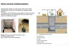
Sedimentation shafts are used as part of the semi-central sedimentation measures in combined and separate sewer systems.
According to ATV-A 166 they are designed to retain any coarse materials carried by the sewage flow, such as coarse sand, gravel and rubble [ATVA166]. (Image: Sedimentation shaft) (Image: Sedimentation shaft - Grabber bucket) Image: Inside view of a settlement shaft [FI-VSB]
left: Debris height indicator
right: Grabber bucket removing … |
|
Decentralised solid retention is defined to include “measures for the retention of solids in the place of their formation before the sewage is fed into the sewage system”. In the opinion of many authors ( [Grott1991] [Giesl1997] [Kraut2000] [Stotz1998] [Somme2004a] [Somme2004] [Fraen2005] [Hilli2005] [SteinR05]) the runoff entering the sewage system from the surface via catch basins is the main source of mineral solids resulting in the formation of … |
|
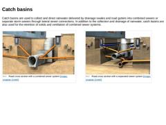
Catch basins are used to collect and direct rainwater delivered by drainage swales and road gutters into combined sewers or separate storm sewers through lateral sewer connections. In addition to the collection and drainage of rainwater, catch basins are also used for the retention of solids and ventilation of combined sewer systems. (Image: Road cross section with a combined sewer system) (Image: Road cross section with a separated sewer system) |
|
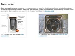
Catch basins with no sump and a direct invert discharge into the sewer line should use a perforated waste bucket as a sieve retaining coarse debris and floatables, before they enter the sewer system. Any particles that can pass through the waste bucket openings are able to reach the main sewer line via the lateral catch basin line [DIN4052:2006]. (Image: Catchbasin detail - direct discharge) (Image: Catch basin - direct discharge) |
|
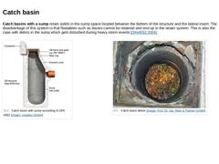
Catch basins with a sump retain solids in the sump space located between the bottom of the structure and the lateral invert. The disadvantage of this system is that floatables such as leaves cannot be retained and end up in the sewer system. This is also the case with debris in the sump which gets disturbed during heavy storm events [DIN4052:2006]. (Image: Catch basin with sump) (Image: Catch basin debris) |
|
|
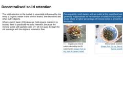
The solid retention in the bucket is essentially influenced by the entry of organic matter in the form of leaves, tree branches and other bulky objects. When a catch basin (CB) does not hold organic matter in its bucket, there is practically no solid retention, because the mineral solids with particle sizes of < 16 mm pass through the slit openings with the slightest volumetric flow. |
Consequently, catch basins with an outlet at the invert level … |
|
|
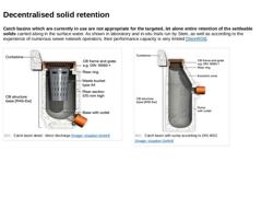
Catch basins which are currently in use are not appropriate for the targeted, let alone entire retention of the settleable solids carried along in the surface water. As shown in laboratory and in-situ trials run by Stein, as well as according to the experience of numerous sewer network operators, their performance capacity is very limited [SteinR08]. (Image: Catchbasin detail - direct discharge) (Image: Catch basin with sump) |
|
Owing to this knowledge, many authors ( [SteinR08] [Artie1988] [Sande1994] [Bromb1993] [Grott1991] [Giesl1997] [Kraut2000] [Stotz1998] [Somme2004a] [Somme2004] [Fraen2005] [Hilli2005]) recommend the replacement of conventional catch basins with new structures that have an improved cleaning function or solid retention. This improved separation of solids from the flow reduces operational requirements by increasing cleaning intervals. |
|
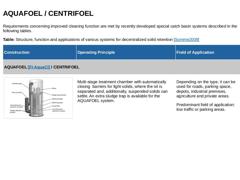
Requirements concerning improved cleaning function are met by recently developed special catch basin systems described in the following tables. Table: Structure, function and applications of various systems for decentralized solid retention [Somme2009] |
Construction |
Operating Principle |
Field of Application |
|
AQUAFOEL [FI-AquaCl] / CENTRIFOEL |
|
(Image: Decentralized solids retention catch basin with improved solids retention) |
Multi-stage treatment … |
|
|
Table: Structure, function and applications of various systems for decentralized solid retention [Somme2009] (Continued) |
Construction |
Operating Principle |
Field of Application |
|
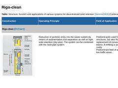
Rigo-clean [FI-Fraen] |
|
(Image: Rigo-clean) |
Reduction of particles entry into the sewer system by means of sedimentation and separation as well as light solid retention (dip tube). The system can be combined with the Sedi-pipe system. |
Predominantly used for newly built … |
|
|
Table: Structure, function and applications of various systems for decentralized solid retention [Somme2009] (Continued) |
Construction |
Operating Principle |
Field of Application |
|
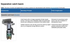
Separation catch basin [FI-ACO] |
|
(Image: Separation catch basin) |
Catch basin with a 3-stage separation (Grate /waste bucket / silt trap) of the settleable solids and particulate bound toxic substances contained in the surface water. Settled material in the silt trap cannot … |
|
|
Table: Structure, function and applications of various systems for decentralized solid retention [Somme2009] (Continued) |
Construction |
Operating Principle |
Field of Application |
|
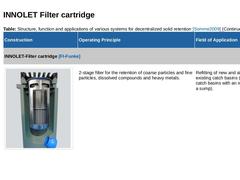
INNOLET-Filter cartridge [FI-Funke] |
|
(Image: INNOLET Filter insert) |
2-stage filter for the retention of coarse particles and fine particles, dissolved compounds and heavy metals. |
Refitting of new and already existing catch basins (conventional catch basins with an invert … |
|
|
Table: Structure, function and applications of various systems for decentralized solid retention [Somme2009] (Continued) |
Construction |
Operating Principle |
Field of Application |
|
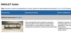
INNOLET-Gutter grate [FI-Sieke] |
|
(Image: Decentralized solids retention) |
Filter cartridge filled with substrate for standard drainage gutters for fine particles and dissolved heavy metals. A coarse particle cartridge is also included for the retention of leaves and coarse … |
|
|
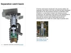
(Image: Separation catch basin) Of all the catch basins introduced in the previous tables, the separation catch basin is the only one that has been developed especially for the decentralised retention of settleable solids. Therefore, it is described in detail in the following section.
Furthermore, the separation catch basin is also appropriate for the limitation of severe water pollution levels because it interrupts the relevant input of particulate … |
|
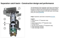
(Image: Separation catch basin components) The development of the separation catch basin was based on the goal of retaining the settleable solids entering the system through the surface runoff, and stopping the remobilisation of solids that are already settled in the catch basin, even during heavy rain events [SteinR08]. Image: Separation catch basin components [FI-ACO] Legend:
1. Grate (Screen / 1st Separation step)
2. Frame,
3. Waste bucket (Sieve / … |
|
(Video: Video:Operating principle of the separation catch basin) |
|
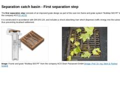
The first separation step iconsists of an improved grate design as part of the cast iron frame and grate system “Multitop 500 PF” by the company ACO [FI-ACO]. It is constructed in accordance with DIN EN 124, and includes a shock absorbing riser which disperses traffic energy into the subsoil thus preventing localised settlement. (Image: Separation catch basin - frame and grate) (Image: Catch basin grate) : Frame and grate “Multitop 500 PF” from … |
|
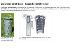
The second separation step is provided by the use of a waste bucket located just below the catch basin grate in accordance with DIN 4052-4. It has the same function as the bucket for a catch basin with invert outlet, that is, it acts as a sieve with predetermined slits and retains particles greater than 16 mm [DIN4052-4:2006]. (Image: Waste bucket type A4 DIN 4052-4) (Image: Separation catch basin - waste bucket) |