
|

|
|

Die Düseneinsätze besitzen einen Bohrungsdurchmesser von 0,3 bis 4,0 mm oder mehr. Die Anzahl der Düseneinsätze kann sowohl gerade als auch ungerade sein. Bei einer ungeraden Anzahl sind nur gleiche Bohrungsdurchmesser zu verwenden, um ein Auswandern der Düse in eine Richtung zu vermeiden. Bei der Verwendung von verschiedenen Bohrungsdurchmessern ist eine gerade Anzahl erforderlich und gleiche Bohrungsdurchmesser sind jeweils gegenüberliegend anzuordnen. |
|

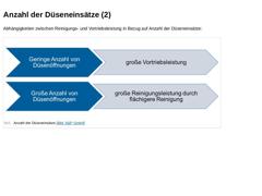
Abhängigkeiten zwischen Reinigungs- und Vortriebsleistung in Bezug auf Anzahl der Düseneinsätze: (Bild: Anzahl der Düseneinsätze) |
|

|
|

-
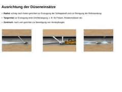
Radial, schräg nach hinten gerichtet zur Erzeugung der Schleppkraft und zur Reinigung der Rohrwandung
-
Tangential zur Erzeugung einer Drehbewegung, z. B. für Fräsen, Rotationsdüsen etc.
-
Zentrisch, nach vorn gerichtet zur Beseitigung von Verstopfungen
(Bild: Radialdüse - Beseitigung von losen Ablagerungen [Bild S&P GmbH]) (Bild: Rotationsdüse - halbradial nach hinten und senkrecht radial strahlend) (Bild: Verstopfungsdüse - Beseitigung von Verstopfungen [… |
|

|
|

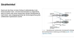
Damit sich die Düse mit dem Schlauch selbstständig in den Kanal einziehen kann, sind die Düseneinsätze so angeordnet, dass ihr Strahl unter einem bestimmten Winkel (Strahlwinkel β) nach hinten, also entgegengerichtet der Strömungsrichtung des zufließenden Spülwassers austritt. (Bild: Darstellung der resultierenden Vortriebskraft in Abhängigkeit des Austrittswinkels in Anlehnung an [FI-Mülle] [Bild S&P]) |
|

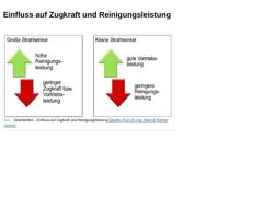
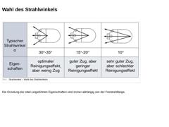
Einen wichtigen Parameter bei der Hochdruckreinigung stellt der Strahlwinkel (auch Austrittswinkel genannt) dar. Der Strahlwinkel ist der eingeschlossene Winkel zwischen Druckwasserstrahl und Rohrachse bzw. Kanallängsachse und kann zwischen 0° und 90° liegen.
Gleichung:
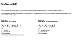
Berechnung der Zugkraft (Formel: Berechnung der Zugkraft) mit: FZ = Zugkraft
FSt = Strahlkraft
β = Strahlwinkel
n = Anzahl der Strahlen (Düseneinsätze) Gleichung:
Berechnung der Reinigungskraft |
|

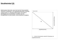
Mathematisch betrachtet, kann die Kraft der Düsenstrahlen vektoriell in Reinigungs- und Zugkraftkomponenten (Vortrieb) zerlegt werden (s. vorherige Gleichungen), das heißt in Abhängigkeit des Strahlwinkels verändern sich die Energieanteile für diese beiden unterschiedlichen Aufgaben. (Bild: Kraft der Düsenstrahlen vektoriell in Reinigungs und Zugkraftkomponenten) |
|

(Bild: Strahlwinkel – Einfluss auf Zugkraft und Reinigungsleistung [Bild S&P GmbH]) |
|

(Bild: Strahlwinkel – Wahl des Strahlwinkels) Die Erzielung der oben angeführten Eigenschaften sind immer abhängig von der Freistrahllänge. |
|

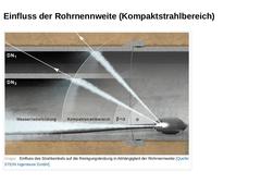
(Bild: Einfluss des Strahlwinkels auf die Reinigungsleistung in Abhängigkeit der Rohrnennweite) |

|

|

|

|
|

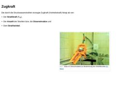
Die durch die Druckwasserstrahlen erzeugte Zugkraft (Vortriebskraft) hängt ab von: (Bild: Düse im Versuchsstand zur Bestimmung des Strahldruckes [FI-KEG]) |
|

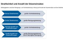
Abhängigkeiten zwischen Reinigungs- und Vortriebsleistung in Bezug auf Anzahl der Düseneinsätze und des Strahlwinkels: (Bild: Anzahl der Düseneinsätze und des Strahlwinkels) |
|

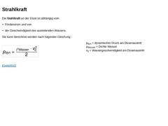
Die Stahlkraft an der Düse ist abhängig vom Sie kann berechnet werden nach folgender Gleichung : (Formel: Dynamischer Druck am Düsenaustritt ) pdyn = dynamischer Druck am Düsenaustritt
ρWasser = Dichte Wasser
v0 = Wassergeschwindigkeit am Düsenaustritt [Geib2002] |
|

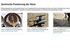
Reinigungsleistung und Zugkraft können noch zusätzlich durch die Montage der Düse auf einem Schlitten bzw. auf Kufen zur Vermeidung des unmittelbaren Kontaktes zwischen Reinigungsdüse und Rohrwandung gesteigert werden. (Bild: Führung der Reinigungsdüse mit Kufen zur Steigerung der Reinigungsleistung) (Bild: Führung der Reinigungsdüse mit Kufen zur Steigerung der Reinigungsleistung 2) (Bild: Führung der Reinigungsdüse mit Schlitten zur Steigerung der … |

|

|

|

Wichtig für einen effektiven Einsatz der Hochdruckreinigung ist die Kenntnis der auftretenden Druckverluste. Dabei unterscheidet man zwischen dem: -
Druckverlust am Fahrzeug,
-
Druckverlust im Hochdruckspülschlauch und dem
-
Druckverlust in der Düse.
Durch die richtige Auswahl des Hochdruckspülschlauches sowie der Düse und Düseneinsätze lassen sich Düsendruck und Volumenstrom optimieren. Dadurch können bei gleicher Pumpenleistung eine schnellere Reinigung … |

|

In der Leitung zwischen dem Ausgang der Hochdruckpumpe und dem Eingang zum Hochdruckschlauch auf der Haspel befindet sich eine Vielzahl von Armaturen und Formstücken. Die Druckverluste am Fahrzeug sind daher abhängig von der jeweiligen Konstruktionsweise und werden in der Literatur mit 5 % des Gesamtverlustes bzw. 12-15 bar angegeben [Geib2002]. |
|

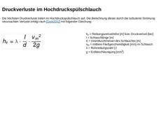
Die höchsten Druckverluste treten im Hochdruckspülschlauch auf. Die Berechnung dieser durch die turbulente Strömung verursachten Verluste erfolgt nach [Geib2002] mit folgender Gleichung: (Formel: Druckverluste im Hochdruckspülschlauch) hv = Reibungsverlusthöhe [m] bzw. Druckverlust [bar]
l = Schlauchlänge [m]
d = Innendurchmesser des Schlauches [m]
vm = mittlere Fließgeschwindigkeit [m/s] im Schlauch
λ = Rohrreibungszahl [-]
g = Erdbeschleunigung [… |
|

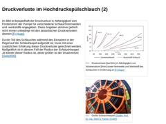
Im Bild ist beispielhaft der Druckverlust in Abhängigkeit vom Förderstrom der Pumpe für verschiedene Schlauchnennweiten und -werkstoffe angegeben. Diese Angaben stimmen jedoch nicht immer unbedingt mit den tatsächlichen Druckverlusten überein [FI-Hugo]. Da ein Teil des Schlauches während des Einsatzes in der Regel auf der Schlauhaspel aufgerollt ist, muss mit einer zusätzlichen Erhöhung dieser Druckverluste gerechnet werden. Maßgeblich ist in diesem … |

|

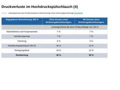
Den Druckverlust im Hochdruckspülschlauch kann man durch Zugabe von Strömungsbeschleunigern reduzieren. Darunter versteht man einen flüssigen Stoff, der die Viskosität des Wassers so verändert, dass die Reibungsverluste minimiert werden. Welche Wirkung auf diese Weise erzielt werden kann, zeigt das nachfolgende Beispiel für Schlauchlängen von 120 m und 240 m in Form von Tabellen. Die abgegebene Motorleistung bildet mit 100 % den Referenzwert [Ney2003]. |
|

(Tabelle: Leistungsverluste des Hochdrucksystems mit/ohne Einsatz eines Strömungsbeschleunigers ) |