|
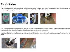
The special adhesive base is stirred in a clean mixing utensil (bucket) with water. The adhesive base must be a thin pulpy consistency. It is applied with a brush onto the cleaned surface to be rehabilitated. | (Image: Adhesive base) | (Image: Mixing utensils for stirring the adhesive base) | (Image: Mixing the adhesive base) | (Image: Adhesive base - applying the thin pulpy adhesive base) |
The KeraLine elements are introduced through the entry shaft (… |
|
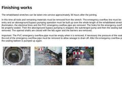
The rehabilitated stretches can be taken into service approximately 36 hours after the jointing. In this time all tools and remaining materials must be removed from the stretch. The emergency overflow line must be sealed of at its entry and an aboveground bypass pumping operation must be built up over the whole length of the rehabilitated stretch. The illumination, the electrical lines and the PVC emergency oveflow pipe are removed. The holes for … |
|
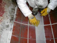
Lining of a DN 1200 sewer with prefabricated segments (vitrified clay elements), which are attached to the host pipe at the invert and cover only the invert area (partial lining with pipe segments). |
|
(Image: 18067 - Titelbild Dokumentation) Process: Grouted-in-place lining process Title: Renovating a masonry ovoid sewer DN 1000/1500 with the TROLINING® process Location: Road in an industrial area with adjoining waste dump and a builder's yard Limiting conditions: - System: Combined wastewater sewer
- Material: Masonry
- Cross section: Ovoid
- Nominal size: DN 1000/1500
- Depth position: 3.0 - 3.5 m
- Groundwater: Not present
- Gradient: 4.2 - 4.5 ‰
- Length of section: …
|
|
Machines and equipment: - 1 Fork lift truck
- 1 Capstan winch
- 1 Compressor
- 4 Uncoiling trestles
- 2 Ovoid inflatable seals
- 6 Circular inflatable sealing seals DN 150-250
- 2 Mixer units (consisting of "Minitainer", main mixer, control unit and 2 post mixers)
- 2 Extruder welding apparatuses
- 2 Angle grinders (electric, pneumatically driven)
- 1 Drilling machine with various attachments
- 1 Pad saw
Tools: - Hammer
- Putty knifes
- Rules
- Carpet and hack knives
- Pointed chisels
|
|
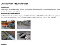
Site equipment Site equipment includes traffic safety, provision and preparation of storage surfaces for equipment and material as well as the provision of power and water supplies. Maintaining the drainage capability In order to maintain the flow, the sewage is pumped through steel pipes of DN 200 laid on the surface from a point upstream to a point downstream of the sections to be renovated. The pipes are joined together by means of quick couplings. |
|
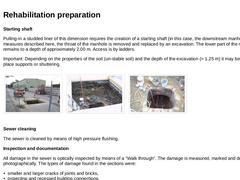
Starting shaft Pulling-in a studded liner of this dimension requires the creation of a starting shaft (in this case, the downstream manhole). For the measures described here, the throat of the manhole is removed and replaced by an excavation. The lower part of the manhole remains to a depth of approximately 2.00 m. Access is by ladders. Important: Depending on the properties of the soil (un-stable soil) and the depth of the excavation (> 1.25 m) it … |
|
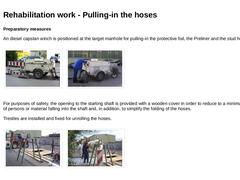
Preparatory measures An diesel capstan winch is positioned at the target manhole for pulling-in the protective foil, the Preliner and the stud hose. | (Image: Target manhole - capstan winch) |
(Image: Target manhole - capstan winch) |
For purposes of safety, the opening to the starting shaft is provided with a wooden cover in order to reduce to a minimum the danger of persons or material falling into the shaft and, in addition, to simplify the folding … |
|
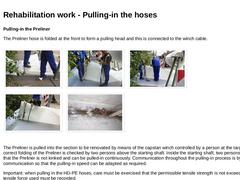
Pulling-in the Preliner The Preliner hose is folded at the front to form a pulling head and this is connected to the winch cable. | (Image: Folding the pulling head for the Preliner: step 1) | (Image: Folding the pulling head for the Preliner: step 2) | (Image: Folding the pulling head for the Preliner: step 3) | | (Image: Folding the pulling head for the Preliner: step 4) | (Image: Winch cable) |
The Preliner is pulled into the section to be renovated by means … |
|
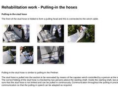
Pulling-in the stud hose The front of the stud hose is folded to form a pulling head and this is connected to the winch cable. | (Image: Folding the pulling head for the stud hose: step 1) | (Image: Folding the pulling head for the stud hose: step 2) | (Image: Folding the pulling head for the stud hose: step 3) | | (Image: Folding the pulling head for the stud hose: step 4) | (Image: Folding the pulling head for the stud hose: step 5) | (Image: Pulling head … |
|
|
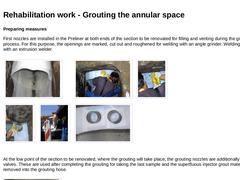
Preparing measures First nozzles are installed in the Preliner at both ends of the section to be renovated for filling and venting during the grouting process. For this purpose, the openings are marked, cut out and roughened for welding with an angle grinder. Welding is carried out with an extrusion welder. | (Image: Installing the grouting nozzles - view into the starting shaft) | (Image: Installing the grouting nozzles - marking the openings for the … |
|
|
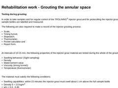
Testing during grouting In order to take samples and for regular control of the TROLINING® injector grout and for protocolling the injector grouting process, sample bottles are labelled and measured. The following are also required to make a record of the injector grouting process: - Scale,
- Timing funnel,
- Stopwatch,
- Thermometer,
- Pocket calculator and
- Report form.
At intervals of 10-15 min, the following properties of the injector grout material are tested … |
|
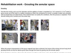
Grouting First the first mixing unit is put into operation and the addition of water is regulated (ca. 3.6 t cement to 1.5 m3 water) until the injector grout comes out of the hose in a watery consistency. When the consistency is correct, a sample is taken and viscosity, density as well as temperature are determined. If the material does not satisfy the conditions, then the process is repeated. The testing of the second mixing unit is carried out … |
|
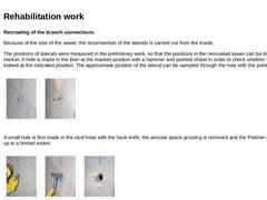
Recreating of the branch connections Because of the size of the sewer, the reconnection of the laterals is carried out from the inside. The positions of laterals were measured in the preliminary work, so that the positions in the renovated sewer can be drawn by a marker. A hole is made in the liner at the marked position with a hammer and pointed chisel in order to check whether the lateral is indeed at the indicated position. The approximate position … |
|
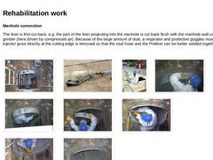
Manhole connection The liner is first cut back, e.g. the part of the liner projecting into the manhole is cut back flush with the manhole wall using an angle grinder (here driven by compressed air). Because of the large amount of dust, a respirator and protective goggles must be worn. The injector grout directly at the cutting edge is removed so that the stud hose and the Preliner can be better welded together. | | | | | | | (Image: Cutting back the liner - … |
|
|
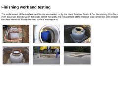
The replacement of the manhole on this site was carried out by the Hans Brochier GmbH & Co, Nuremberg. For this purpose, an even base was bricked up on the lower part of the shaft. The replacement of the manhole was carried out with prefabricated concrete elements. Finally the road surface was replaced. | (Image: Making a base for the bottom of the manhole with bricks) | (Image: Raising the manhole with prefabricated concrete elements) | (Image: Raising … |
|
|
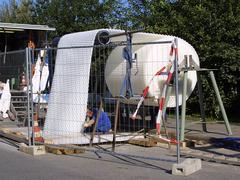
Lining of an ovid sewer DN 1000/1500 with a deflection-resistant annular gap made of load-bearing cement mortar grouting (TROLINING® preliner system), produced by injection behind a plastic inner layer which is permanently anchored to the grouting (lining with a rigidly anchored inner plastics layer). |