
|

|
|

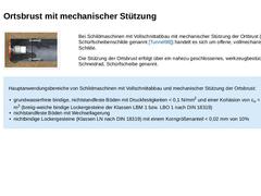
(Bild: Schildmaschine mit Vollschnittabbau - Ortsbrust mit mechanischer Stützung (SM-V2)) Bei Schildmaschinen mit Vollschnittabbau mit mechanischer Stützung der Ortbrust (auch Schürfscheibenschilde genannt [Tunnel98]) handelt es sich um offene, vollmechanisierte Schilde. Die Stützung der Ortsbrust erfolgt über ein nahezu geschlossenes, werkzeugbestücktes Schneidrad, Schürfscheibe genannt. Hauptanwendungsbereiche von Schildmaschinen mit Vollschnittabbau … |
|

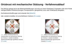
Das Bohrgut gelangt durch die Bodeneintrittsöffnungen und wird von einem Förderband, Kratzketten oder einer Förderschnecke an nachgeschaltete Fördereinrichtungen (Transportkarren, gleisgeführte Loren oder Förderband) übergeben. Die Bodeneintrittsöffnungen sind entweder fest [Akker01] oder variabel einstellbar mit verschließbaren Sektoren [FI-Lovata]. (Bild: Offene Schildmaschinen mit Schürfscheibe und mechanischer Stützung der Ortsbrust - Variabel einstellbare … |

|

|

|

| (Bild: Schildmaschine mit Vollschnittabbau - Ortsbrust mit Druckluftstützung (SM-V3))
|
Beim Vortrieb im Grundwasser muss bei offenen Schildmaschinen der Bauarten SM-V1 sowie SM-V2 die Ortsbrust dauerhaft, d.h. über die gesamte Vortriebslänge mit Druckluft beaufschlagt bzw. zum geschlossenen Schild übergegangen werden, sofern es nicht abgesenkt werden kann bzw. darf [Tunnel98]. | |
Hauptanwendungsbereich von Schildmaschinen mit Vollschnittabbau und … |
|

|

|
|

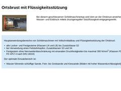
(Bild: Schildmaschine mit Vollschnittabbau - Ortsbrust mit Flüssigkeitsstützung (SM-V4)) Bei diesem geschlossenen Schildmaschinentyp wird dem an der Ortsbrust anstehenden Wasser- und Erddruck mittels druckgeregelter Stützflüssigkeit entgegengewirkt. Hauptanwendungsbereiche von Schildmaschinen mit Vollschnittabbau und Flüssigkeitsstützung der Ortsbrust: -
alle Locker- und Festgesteine (Klassen LN und LB) bis Zusatzklasse S2
-
bei Verwendung eines Felsbohrkopfes: …
|
|

|
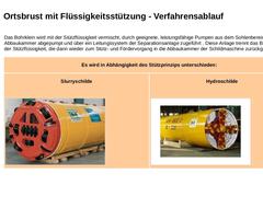
Das Bohrklein wird mit der Stützflüssigkeit vermischt, durch geeignete, leistungsfähige Pumpen aus dem Sohlenbereich der Abbaukammer abgepumpt und über ein Leitungssystem der Separationsanlage zugeführt . Diese Anlage trennt das Bohrklein von der Stützflüssigkeit, die dann wieder zum Stütz- und Fördervorgang in die Abbaukammer der Schildmaschine zurückgeführt wird. |
|
Es wird in Abhängigkeit des Stützprinzips unterschieden: |
|
Slurryschilde (Bild: Slurryschild … |
|
|

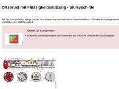
Bei den Slurryschilden erfolgt die Stützdrucksteuerung innerhalb der Abbaukammer durch den über Pumpen gesteuerten Zu-und Abfluss der Stützflüssigkeit. (Bild: Plus/Minus)Nachteil von Slurryschilden: |
|
|

|
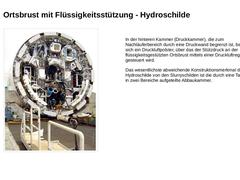
(Bild: Hydroschild ohne Bohrkopf) |
In der hinteren Kammer (Druckkammer), die zum Nachläuferbereich durch eine Druckwand begrenzt ist, befindet sich ein Druckluftpolster, über das der Stützdruck an der flüssigkeitsgestützten Ortsbrust mittels einer Druckluftregelanlage gesteuert wird. Das wesentlichste abweichende Konstruktionsmerkmal der Hydroschilde von den Slurryschilden ist die durch eine Tauchwand in zwei Bereiche aufgeteilte Abbaukammer. |
|
|

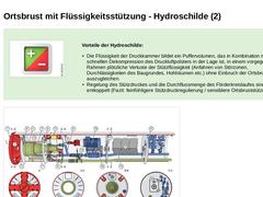
Vorteile der Hydroschilde: -
Die Flüssigkeit der Druckkammer bildet ein Puffervolumen, das in Kombination mit der schnellen Dekompression des Druckluftpolsters in der Lage ist, in einem vorgegebenen Rahmen plötzliche Verluste der Stützflüssigkeit (Anfahren von Störzonen, Durchlässigkeiten des Baugrundes, Hohlräumen etc.) ohne Einbruch der Ortsbrust auszugleichen.
-
Regelung des Stützdruckes und die Durchflussmenge des Förderkreislaufes …
|

|

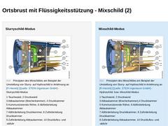
Ein Mixschild ist eine flüssigkeitsgestützte Schildmaschine für vielschichtige, komplexe Geologien, insbesondere mit hohem Wasseranteil und hohen Wasserdrücken. Ausgangsbasis für den Mixschild ist das Prinzip des Hydroschildes. Er kann sowohl im Slurry als auch im Mixschild-Modus gefahren werden. Eine Bentonit-Suspension dient zur Stützung der Ortsbrust und gleichzeitig als Fördermedium. Die exakte Regulierung des Stützdrucks erfolgt dabei nicht … |
|

Slurryschild-Modus (Bild: Prinzipien des Mixschildes am Beispiel der Umstellung von Slurry- auf Hydroschild in Anlehnung an [FI-Herreb] [Bild: S&P GmbH] - Slurryschild-Modus) Mixschild-Modus (Bild: Prinzipien des Mixschildes am Beispiel der Umstellung von Slurry- auf Hydroschild in Anlehnung an [FI-Herreb] [Bild: S&P GmbH] - Hydroschild- bzw. Mixschild-Modus) |
|

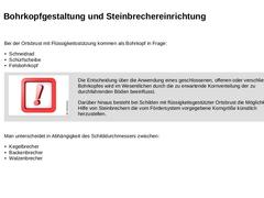
Bei der Ortsbrust mit Flüssigkeitsstützung kommen als Bohrkopf in Frage: -
Schneidrad
-
Schürfscheibe
-
Felsbohrkopf
|
|
Wichtig:
Die Entscheidung über die Anwendung eines geschlossenen, offenen oder verschließbaren Bohrkopfes wird im Wesentlichen durch die zu erwartende Kornverteilung der zu durchfahrenden Böden beeinflusst.
Darüber hinaus besteht bei Schilden mit flüssigkeitsgestützter Ortsbrust die Möglichkeit, mit Hilfe von Steinbrechern die vom … |
|
|

|
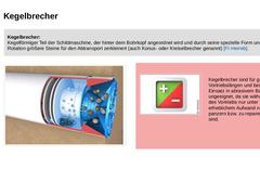
Kegelbrecher:
Kegelförmiger Teil der Schildmaschine, der hinter dem Bohrkopf angeordnet wird und durch seine spezielle Form und Rotation größere Steine für den Abtransport zerkleinert (auch Konus- oder Kreiselbrecher genannt) [FI-Herreb]. |
|
|
|
(Bild: Umstellungsversionen des EPB UNCLEMOLE - Prinzipskizze Slurryschild-Modus in Anlehnung an [FI-Isekib] [Bild: S&P GmbH]) |
(Bild: Plus/Minus)
Kegelbrecher sind für große Vortriebslängen und beim Einsatz … |
|
|

Backenbrecher:
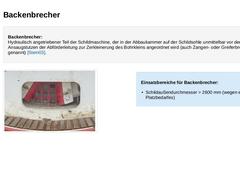
Hydraulisch angetriebener Teil der Schildmaschine, der in der Abbaukammer auf der Schildsohle unmittelbar vor dem Ansaugstutzen der Abförderleitung zur Zerkleinerung des Bohrkleins angeordnet wird (auch Zangen- oder Greiferbrecher genannt) [Stein03]. (Bild: Auf der Schildsohle angeordneter Backenbrecher mit Rechen) Einsatzbereiche für Backenbrecher: -
Schildaußendurchmesser > 2600 mm (wegen erhöhten Platzbedarfes)
|
|

Walzenbrecher:
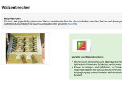
Ein aus zwei gegenläufig rotierenden Walzen bestehender Brecher, der unmittelbar zwischen Rechen und Ansaugstutzen der Abförderleitung installiert ist (auch Durchlaufbrecher genannt) [Stein03]. (Bild: Ausgebauter Walzenbrecher (System MOCO [FI-Moco]) eines Hydroschildes mit einem Schildaußendurchmesser von 1966 mm [FI-Dywida]) (Bild: Plus/Minus) Vorteile von Walzenbrechern: -
können auch zerrissenes und abgespantes Holz in hydraulisch förderbare …
|
|

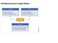
(Bild: Mögliche verfahrenstechnische Probleme bei hohem Verklebungspotenzial bindiger Böden in Anlehnung an [Sager00] [Bild: S&P GmbH]) |
|

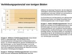
(Bild: Indikationsbereiche für das Verklebungspotenzial von Tonböden in Abhängigkeit der Plastizitätszahl IP und der Konsistenzzahl IC in Anlehnung an [Thewe99] [Bild: S&P GmbH]) Gruppe 2 - Mittleres Verklebungspotenzial: Diese Böden führen zu Behinderungen, die sich jedoch durch Zusatzmaßnahmen mit begrenztem Umfang beherrschen lassen. Zu solchen Maßnahmen gehören Modifikationen an den Werkzeugen, an den Spüleinrichtungen und an der Leistung des … |
|

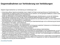
Mögliche Gegenmaßnahmen zur Verhinderung von Verklebungen sind: -
Verwendung offener Speichenschneidräder (wenn möglich mit Felge) anstatt geschlossener Schürfscheiben bzw. Felsbohrköpfe mit möglichst großen Räumerschlitzen bis ins Zentrum, um eine geringere Haftfläche zu bieten sowie einen möglichst ungehinderten Bodeneintrag zu gewährleisten.
-
Besatz des Bohrkopfes mit schneidend-schälenden Abbauwerkzeugen (Schälmessern), um eine die Verklebung …
|
|
|

|
|

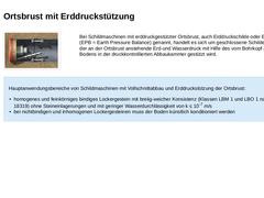
(Bild: Schildmaschine mit Vollschnittabbau - Ortsbrust mit Erddruckstützung (SM-V5)) Bei Schildmaschinen mit erddruckgestützter Ortsbrust, auch Erddruckschilde oder EPB-Schilde (EPB = Earth Pressure Balance) genannt, handelt es sich um geschlossene Schilde, bei denen der an der Ortsbrust anstehende Erd-und Wasserdruck mit Hilfe des vom Bohrkopf abgebauten Bodens in der druckkontrollierten Abbaukammer gestützt wird. Hauptanwendungsbereiche von Schildmaschinen … |
|

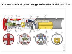
(Bild: Erddruckschild vom Typ EPB 1500 (Außendurchmesser 1830 mm) mit Wagenförderung in Anlehnung an [FI-Herreb] [Bild: S&P GmbH] - Längs- und Querschnitte) |
|

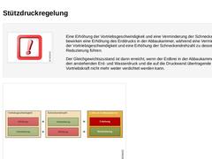
Eine Erhöhung der Vortriebsgeschwindigkeit und eine Verminderung der Schneckendrehzahl bewirken eine Erhöhung des Erddrucks in der Abbaukammer, während eine Verminderung der Vortriebsgeschwindigkeit und eine Erhöhung der Schneckendrehzahl zu dessen Reduzierung führen. Der Gleichgewichtszustand ist dann erreicht, wenn der Erdbrei in der Abbaukammer durch den anstehenden Erd- und Wasserdruck und die auf die Druckwand übertragende Vortriebskraft … |
|

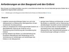
Beim Einsatz von Erddruckschilden muss der zu durchfahrende Boden bzw. der als Stützmittel genutzte Erdbrei die in der Tabelle aufgeführten Eigenschaften aufweisen.
|
(Tabelle: Anforderungen an den Baugrund und den Erdbrei für den Einsatz von Erddruckschilden [FI-Steina]) |
|