|

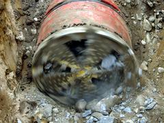
Micro tunnelling refers to unmanned, remote-controlled methods for jacking pipes.
This module covers the various methods, in particular, micro tunnelling with hydraulic, pneumatic, auger and scraper conveyance and soil displacement. The focus is on removal and processing the spoil, drive variants of the cutting head, cutting head design, application in groundwater, measures to reduce jacking forces and measures to remove obstacles.
After completion of this module, you will have a sound knowledge of:
- cutting head design;
- processing of the spoil in separation plants;
- measures to reduce jacking resistance; and
- dealing with obstacles.
|
|

Today, supply and discharge lines are still predominantly installed by using the open-cut method: a trench is dug, the lines are installed. Under the protection of an embankment or sheeting and the trench is filled afterwards. In the face of the numerous disadvantages as well as the citizens' growing environmental consciousness in the future it is urgently necessary to take trenchless technology into account much stronger than until today as an alternative … |
|

| (Image: Attention!)
|
The special feature of the steerable method of trenchless installation of cables and pipes by jacking or boring is that the whole pipe string in the form of a series of linked elements behind the microtunnelling machine or shield machine or the flexible drill rod must follow the boring or displacement head. Thus the bore path must necessarily also be the line and gradient of the final line. This means that all deviations from … |
|
|

|
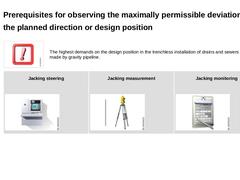
(Image: Attention!) The highest demands on the design position in the trenchless installation of drains and sewers are made by gravity pipeline. |
|
Jacking steering (Image: Steering of a jacking) |
Jacking measurement (Image: Measurement of a jacking) |
Jacking monitoring (Image: Documentation) |
|
|

|
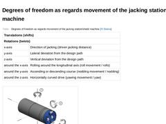
(Table: Degrees of freedom as regards movement of the jacking station/shield machine [FI-Steina]) |
|
(Image: Degrees of freedom as regards movement of a jacking station with reference to [Schad03] - NEU) |
|

|

|
|

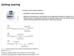
(Image: Steering of a jacking) Functions of the jacking steering: -
possibility of directional changes
-
definition of the ideal size and duration of the steering movement re-achieve or maintain the design position by taking into account the specific values of the soil and the machine in manual steering and/or their calculation in automatic steering
(Image: Incorrect steering in the vertical or horizontal plane for straight line jacking [Scher77a]) |
|

|
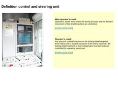
(Image: Control and steering unit) |
Main operator's stand:
Operator's stand, from where the boring process and the forward movement of the shield machine are controlled. [DINEN12336:2010] |
Operator's stand:
Any place of a shield machine or the trailing shield segment, from where one or several functions of the shield machine, the trailing shield machine or their independent function units are controlled by operating personnel. [DINEN12336:2010] |
…
|
|

|
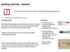
(Image: Attention!) With reference to the machine, different variants of jacking steering are used. |
|
(Table: Steering variants for jacking steering [FI-Steina]) |
|
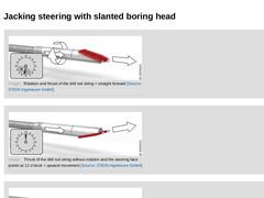
(Image: Rotation and thrust of the drill rod string = straight forward) |
|
(Image: Principle of displacement and steering of the ACEMOLE PL 30 with reference to [Manab98] [Image: S&P GmbH] - Tilting the displacement and steering head) |
|
(Image: ULTIMATE METHOD - arrangement of the articulations … |
|
|
|

|
(Image: Rotation and thrust of the drill rod string = straight forward) |
|
|
|
(Image: Thrust of the drill rod string without rotation and the steering face points at 12 o'clock = upward movement) |
|
|
|
(Image: Thrust of the drill rod string without rotation and the steering face points at 6 o'clock = downward movement) |
|
|

(Video: Displacement- and steering principle of the ACEMOLE PL 30) Video: Steering of the shield machine by means of steering cylinders [Image: S&P GmbH]. This interactive object is only visible online. |
|

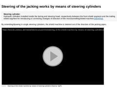
Steering cylinder:
Hydraulic cylinders installed inside the boring and steering head, respectively between the front shield segment and the trailing shield segment for introducing or correcting changes of direction of the microtunnelling/shield machine (not found). By extending/drawing in single steering cylinders, the shield machine is steered out of the direction of the jacking pipes. (Video: Steering of the shield machine by means of steering cylinders) |
|

The actual problem in steering is the determination of the size of the steering movement (e.g. stroke of the individual steering cylinders or the setting of the slanted side of the displacement or boring head or the angled steering head) on recognition of a deviation from the determined line and gradient. |
|
(Image: Attention!) With microtunnelling or pipe jacking, abrupt changes of direction and steering corrections should be avoided as these can … |
|
|

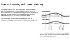
During the steering itself, it must be taken into account that after the introduction of the steering process, the boring or displacement head or the microtunnelling or shield machine will still cover a certain distance in the old (incorrect) direction before the directional correction comes into effect. This means that the required countersteering must be introduced already before reaching the prescribed design path. (Image: Principle of the series … |
|

|
|

|
(Image: Measurement of a jacking)
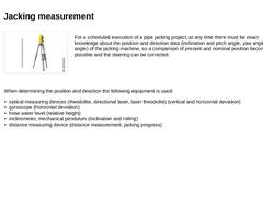
For a scheduled execution of a pipe jacking project, at any time there must be exact knowledge about the position and direction data (inclination and pitch angle, yaw angle, rolling angle) of the jacking machine, so a comparison of present and nominal position becomes possible and the steering can be corrected. |
When determining the position and direction the following equipment is used: -
optical measuring devices (…
|
|

|

|
|

|
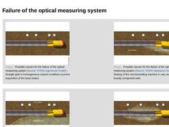
(Image: Possible causes for the failure of the optical measuring system - Straight path in homogeneous subsoil conditions (correct acquisition of the laser beam)) (Image: Possible causes for the failure of the optical measuring system - Sinking of the microtunnelling machine in very soft or loosely compacted soils) |
|
|
|
(Image: Possible causes for the failure of the optical measuring system - Grinding cut through differing hardnesses of stratified … |
|
|

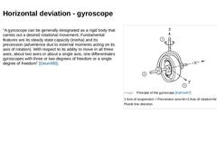
"A gyroscope can be generally designated as a rigid body that carries out a desired rotational movement. Fundamental features are its steady state capacity (inertia) and its precession (advertence due to external moments acting on its axis of rotation). With respect to its ability to move in all three axes, about two axes or about a single axis, one differentiates gyroscopes with three or two degrees of freedom or a single degree of freedom" [Deuml80]. |
|

|
In trenchless installation, use is made of the declination gyroscope, also called simply a gyroscope, north seeking gyro compass, north seeker, or meridian display [Sachs95] [Stras83] [Künze71].
The jacking or shield machine is generally stopped for measurement (North seeking) in order not to disturb the course of the direction measurement. The length of time for measurement is approximately two to five minutes.
For microtunnelling and pipe jacking, … |
|
|

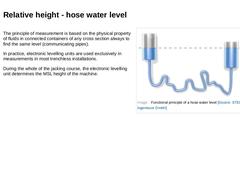
The principle of measurement is based on the physical property of fluids in connected containers of any cross section always to find the same level (communicating pipes). In practice, electronic levelling units are used exclusively in measurements in most trenchless installations. During the whole of the jacking course, the electronic levelling unit determines the MSL height of the machine. (Image: Functional principle of a hose water level) |
|

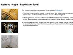
(Image: Hose of the hose water level (green) within the pipe string) (Image: Determination of position and direction) (Image: Position determination - Reference module of the hose level (height level always above the level of the tunnelling machine)) The electronic levelling unit consists of three modules [FI-Bodenb]: |
|

|
|

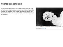
Mechanical pendulums can be used for jacking methods with an illuminated target board and picture transmission by a video camera. The required angle is read off using the monitor; an electrical signal that can be evaluated for automatic steering is not received. (Image: Mechanical pendulum for measuring changes in the angle of inclination [Stein87g]) |

|

|