
|

|
(Image: Soil removal techniques) |
|
(Image: Microtunnelling with auger spoil removal) |
|
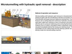
(Image: Microtunnelling with hydraulic spoil removal) |
|
(Image: Microtunnelling with pneumatic spoil removal) |
|
The unmanned, steerable microtunnelling techniques employed base generally on the principle of soil removal. Depending on the way of conveying the spoil, it is differentiated between: |
|
|
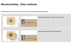
Furthermore, there are two other, not very common microtunnelling techniques. |
|
(Image: Soil removal techniques) |
(Image: Microtunnelling with spoil removal by other mechanical means (spoil removal by a scraper arrangement)) |
Microtunnelling with scraper spoil removal |
|
(Image: Soil displacement techniques) |
(Image: Microtunnelling with soil displacement) |
Microtunnelling with soil displacement |
|

|
|

|
|
(Image: Technical components in microtunnelling) |
|
(Image: Equipment, possible arrangement of the technical components on the construction site and space requirement in microtunnelling with auger spoil removal - top view) |
The technical components employed in microtunnelling vary depending on the way the spoil or cuttings are removed. The following components are employed with all kinds of microtunnelling: -
jacking station (consisting of jacking frame, …
|
|
|
|
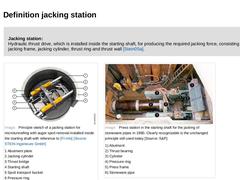
Jacking station:
Hydraulic thrust drive, which is installed inside the starting shaft, for producing the required jacking force, consisting of jacking frame, jacking cylinder, thrust ring and thrust wall [Stein05a]. |
|
(Image: Principle sketch of a jacking station for microtunnelling with auger spoil removal installed inside the starting shaft) (Image: Press station in the starting shaft for the jacking of stoneware pipes in 1980) |
|
|
|
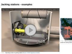
(Video: Operating mode of a jacking station)
| (Image: View of a jacking station for microtunnelling that is mounted inside the starting shaft)
| | (Image: Jacking station)
| (Image: Jacking station with abutment plate)
|
|
|
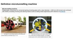
Microtunnelling machine:
Displaceable construction for unmanned jacking of jacking pipes with a clear diameter < 1200 mm (48 in) (not to be confused with DN/ID) consisting of boring and steering head as well as trailing shield segment(s) (with reference to [DS853]). (Image: Example of a tunneling machine with drilling and control head and back-up) (Image: View from behing into the open control head of a LOVAT-MTS tunneling machine) |
|
|
(Image: Attention!)
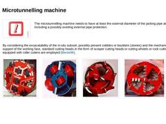
The microtunnelling machine needs to have at least the external diameter of the jacking pipe at least including a possibly existing external pipe protection. |
|
By considering the excavatability of the in-situ subsoil, possibly present cobbles or boulders (stones) and the mechanical support of the working face, standard cutting heads in the form of scraper cutting heads or cutting wheels or rock cutting heads equipped with roller … |
|

|
|
(Image: Attention!) |
In microtunnelling the whole pipe string in the form of a linked chain must follow the microtunnelling machine. Thus the bore path must necessarily also be the line and gradient of the final line. This means that all deviations from the design position remain almost unchanged as errors. |
|
(Video: Principle of linked chain during jacking) Video: Principle of linked chain during jacking [Image: S&P GmbH]. This interactive object … |
|

|
Steerability (also known as controllability) is achieved because the microtunnelling machine consists of two parts linked together by an articulated joint - the boring/ steering head and the trailing shield segment. The steering head can be angled in any direction by means of steering cylinders operated from a control and steering desk. (Video: Steering of the shield machine by means of steering cylinders) Video:Steering of the shield machine by means … |
|
|
(Image: Examples of cross sectional shapes of starting shafts in microtunnelling [FI-Herreb] - Circular (open sinking shaft), jacking cylinder arranged parallel to the jacking pipe/to the microtunnelling machine) |
|
(Image: Entry of the microtunnelling machine into the target shaft) |
|
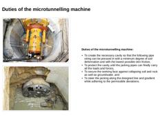
Duties of the microtunnelling machine: -
To create the necessary cavity so that the following pipe string can be pressed in with a minimum degree of soil deformation …
|
|

|
|
(Image: Control and steering unit) |
Main operator's stand:
Operator's stand, from where the boring process and the forward movement of the shield machine are controlled [DINEN12336:2010]. |
|
Operator's stand:
Any place of a shield machine or the trailing shield segment, from where one or several functions of the shield machine, the trailing shield machine or their independent function units are controlled by operating personnel [DINEN12336:2010] |
|

|
|
|
|

|
|
Area of application of microtunnelling methods with auger spoil removal: -
nominal pipe size range of DN/ID 250 to DN/ID 1000 (10 in to 40 in) and jacking distances of up 150 m (500 ft)
-
straight borings, usually loose soil of the soil classes L (stone classes up to S2) according to DIN 18319, in groundwater up to 6 m with additional equipment
-
recommended area of application for a controlled mechanical support of the working face ≤ DN/ID 800 (32 …
|
|
|
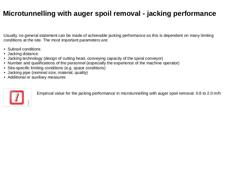
Usually, no general statement can be made of achievable jacking performance as this is dependent on many limiting conditions at the site. The most important parameters are: -
Subsoil conditions
-
Jacking distance
-
Jacking technology (design of cutting head, conveying capacity of the spiral conveyor)
-
Number and qualifications of the personnel (especially the experience of the machine operator)
-
Site-specific limiting conditions (e.g. space conditions)
|
|

|
|
(Image: Pros and cons)
(Table: Advantages and disadvantages of microtunnelling with auger spoil removal) |
|

|
|
|
|
|
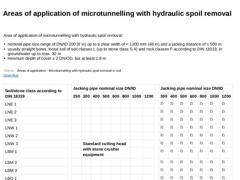
Area of application of microtunnelling with hydraulic spoil removal: -
nominal pipe size range of DN/ID 200 (8 in) up to a clear width of < 1200 mm (48 in) and a jacking distance of ≤ 500 m
-
usually straight bores, loose soil of soil classes L (up to stone class S 4) and rock classes F according to DIN 18319, in groundwater up to max. 30 m
-
minimum depth of cover ≥ 2 DN/OD, but at least 1.8 m
(Table: Areas of application of microtunnelling with hydraulic … |
|
|
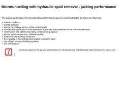
The jacking performance of microtunnelling with hydraulic spoil removal is subject to the following influences: -
subsoil conditions
-
jacking distance
-
jacking technology (design of the cutting head)
-
number and qualification of the personnel (especially the experience of the machine operator)
-
construction-site-specific boundary conditions (e.g. space)
-
jacking pipe (nominal size, material quality)
-
additional and auxiliary measures
-
the capacity …
|
|
|
|
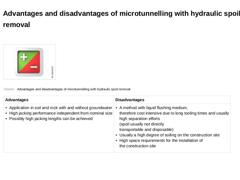
(Image: Pros and cons)
(Table: Advantages and disadvantages of microtunnelling with hydraulic spoil removal) |
|
|
|

|
|
(Image: Microtunnelling with pneumatic spoil removal) |
|
(Image: Equipment, possible arrangement of the components on the construction site and space requirements (approximately L x W = 34 x 4 m) in microtunnelling with pneumatic spoil removal - plan view (on the model of the jacking of pipes DN/ID 600, pipe length 2.0 m)) |
|
Method of operation and sequence Microtunnelling with pneumatic spoil removal on the basis of a suction plant is characterized … |
|

|
Experience gathered at sites [Reith98] has shown that they are at their best in cohesive soils with a large percentage of particle sizes < 0.5 mm. The main advantages here are economic as the separation plants required with hydraulic spoil removal for separating the slurry are less effective in this size range. Area of application of microtunnelling with pneumatic spoil removal: -
nominal pipe size range of DN/ID 200 (8 in) up to a clear width < 1200 …
|
